AutoAirSpring
Air springs are commonly used in trucks, buses, and rail vehicles because their internal air pressure can be increased or decreased to adjust for the load carried while maintaining ride height.
Typically a valve on the chassis is mechanically linked to an axle and if the ride height is too low the value opens to admit high pressure air to the spring from a compressor, until the ride height increases enough to close the value. Conversely if the ride height is too high the value vents air from the spring to atmosphere until the ride height decreases enough to close the value. The value has a dead band so that typical suspension ride and roll motions do not open the valve.
In some cases, air springs are used as actuators to lower and raise an axle and tires. When a truck is heavily loaded, the air spring is inflated to push the axle's tires into the road and spread the load over a greater area of road.
In other cases, air springs may connect with each other or to a reservoir. The additional volume of a reservoir, for example, decreases the spring rate since for a change in ride height the incremental change in volume as fraction of the total volume is smaller. When springs connect to one another or to a reservoir, then the resistance to flow between the springs or the spring and reservoir may be tuned to give a frequency dependent response.
AutoAirSpring Property Files
AutoAirSpring properties are stored in a TeimOrbit format property file containing a table of the spring force verses spring height for different at different static pressures. When you submit your model to the solver, MotionSolve reads the air spring properties from the file for use during the simulation. If the units specified in air spring property file differ from the model, MotionSolve converts the air spring properties to model units, however it leaves the property file unchanged. See AutoAirSpring to learn more about TeimOrbit format property files.
Connecting an AutoAirSpring
-
Similarly, select the second point.
Typically, air springs act between the chassis and an axle. Point 1 on Body 1 defines the top of the air spring, while Point 2 on Body 2 defines the bottom of the air spring as shown in Connecting an AutoAirSpring:
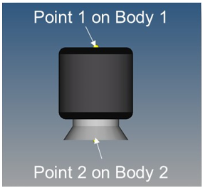
Figure 1.
TeimOrbit File for AutoAirSpring
Example TeimOrbit file for AutoAirSpring.
The different blocks available in the TeimOrbit file are described in the following headings.
Header
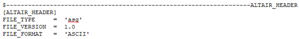
Figure 2.
Units
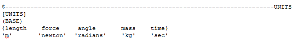
Figure 3.
Parameters
- Torus Major Radius = Inner Diameter/2+(Bag Diameter-Inner Diameter)/4
- Torus Minor Radius = (Bag Diameter-Inner Diameter)/4
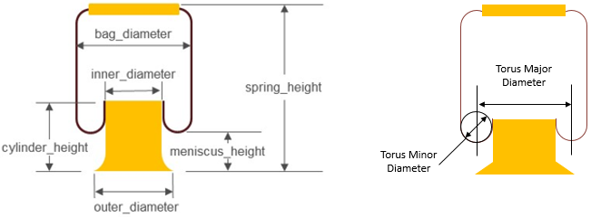
Figure 4.
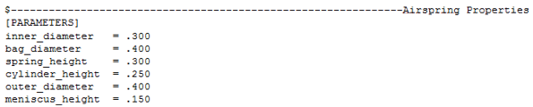
Figure 5.
AirSpring
- Z_DATA
- XY_DATA
The Z_DATA sub-block gives the nominal internal spring pressure for each force verses deflection curve. The XY_DATA sub-block contains multiple force verses deflection curves.
The first column of the XY_DATA sub-block (in the example below) is spring height and each subsequent column is the spring force for one pressure defined in the Z_DATA sub-block. Therefore the forces in the second column correspond to the first internal pressure (137875 Newton/Meter2), and the forces in the third column correspond to the second internal pressure (275790 Newton/Meter2), and so on.
The spring height provided in the first column should cover the full range of the air spring heights. During a simulation if the spring height outside the range of height provided, MotionSolve linearly extrapolates the spring force with spring height.
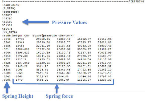
Figure 6.