Driver Demand File (DDF)
You can define the driver path as a table of centerline points in Cartesian coordinates.
Driver uses the AKIMA interpolation scheme to interpolate between the nodes.
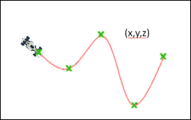
Figure 1.
Figure 1.
[ALTAIR_HEADER]
FILE_TYPE = 'DDF'
FILE_VERSION = 1.0
FILE_FORMAT  = 'ASCII'
 [UNITS]
(BASE)
{length  force      angle       mass    time}
'm'   'newton'   'degrees'   'kg'    'sec'
 [DEMAND_VECTORS]
{X                Y                 Z}
2.1000            0.0000            0.0000
1.1000            0.1050            0.0000
0.1001            0.2200            0.0000
-0.8995           0.3451            0.0000
-1.8989           0.4803            0.0000
-2.8979           0.6256            0.0000
-3.8964           0.7810            0.0000
-4.8942           0.9466            0.0000
-5.8913           1.1224            0.0000
-6.8876           1.3084            0.0000
-7.8830           1.5046            0.0000
-8.8773           1.7111            0.0000
-9.8705           1.9278            0.0000
-10.8624          2.1549            0.0000
-11.8530          2.3922            0.0000
Defining acceleration or velocity profile in a DDF.
Example
[DEMAND_ACC]
TYPE = 'CURVE'
FILE = 'xyz_demand_acc_fo8.ddf'
DEMAND_VECTOR = 'DEMAND_ACC'
[DEMAND_VECTORS]
{X    Y     Z     DA}
0     0     0     3
-1    0     0     3
-2    0     0     3
-3    0     0     3
-4    0     0     3
-5    0     0     3
-6    0     0     3
-7    0     0     3
-8    0     0     3
-9    0     0     3
-10   0     0     3
-11   0     0     3
-12   0     0     3
-13   0     0     3
-14   0     0     3
-15   0     0     3
The demand acceleration signal from the DDF can be accessed by the demand acceleration
block in the ADF as shown
below.
$-----------------------------------------------------------DEMAND_ACC
[DEMAND_ACC]
TYPE = 'CURVE'
FILE = 'example.ddf'
DEMAND_VECTOR = 'DA'