HM-2040: Create and Edit Line Data
Sometimes CAE users need to create models from sketches where there is no pre-existing geometry. The tools in this tutorial will help you accomplish that task.
- Create circle, arc, line, and tangent lines
- Duplicate and translate lines
- Edit lines by splitting and displaying their IDs
- Delete redundant arcs and lines
- Duplicate and reflect an arc
- Create a surface square and two parallel lines on an X-Y plane
- Create a fillet between two lines
- Exporting geometry in IGES format
Create a Component Collector
In this step you will create a component collector to geometry.
- To create a component, right-click in the Model Browser and select from the context menu, or click from the menu bar.
- In the Create Component dialog, type geometry in the Name field.
- Click the Color swatch and select yellow from the box of colors.
- Click Create.
Create Nodes
In this step you will create nodes.
-
On the Standard toolbar, click
 .
.
-
Enter the following X, Y, and Z coordinates listed in the table below to create
five nodes.
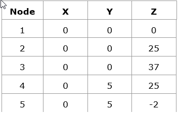
Figure 1.
Display the Node IDs
In this step you will display the node IDs.
-
To open the Numbers panel, click
 on the Display toolbar.
-
Click on.
HyperMesh displays the node IDs.
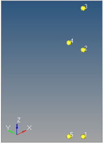
Figure 2.
Create a Circle
In this step you will create a circle.
-
Click create.
HyperMesh creates the circle's center. Your circle may look different.
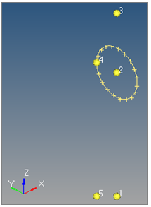
Figure 3.
Create an Arc
In this step you will create an arc.
-
To open the Arc Center and Radius subpanel, click
 .
.
-
On the Standard toolbar, click
 .
.
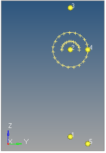
Figure 4.
Create a Line
In this step you will create a line.
-
To open the Linear Nodes subpanel, click
 .
.
-
Click create.
HyperMesh creates a line between nodes 4 and 5.
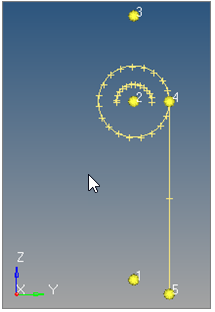
Figure 5.
Duplicate and Translate Lines
In this step you will duplicate and translate lines.
-
Click translate-.
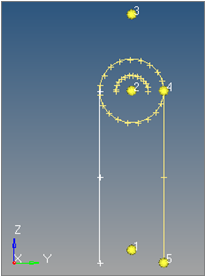
Figure 6.
Edit Lines by Splitting
In this step you will edit lines by splitting at a line.
-
Select the top, right curved line of the circle indicated in the following
image.
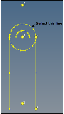
Figure 7.
Display the Line IDs
In this step you will display the line IDs.
Delete a Redundant Arc
In this step you will delete a redundant arc.
-
To open the Delete panel, click
 on the
Collectors toolbar, or press F2.
on the
Collectors toolbar, or press F2.
-
Select the bottom right curved line of the circle indicated in the following
image.
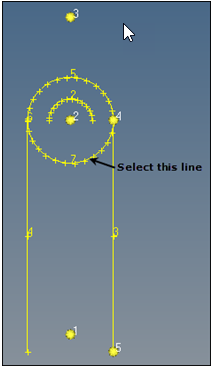
Figure 8.
Duplicate and Reflect an Arc
In this step you will duplicate and reflect an arc.
-
Click return.
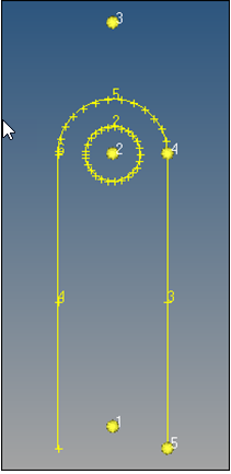
Figure 9.
Create Tangent Lines
In this step you will create two tangent lines.
-
To exit the panel, click return.
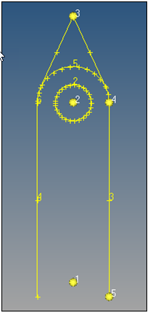
Figure 10.
Redisplay Line IDs
In this step you will redisplay the line IDs.
Split Curves
In this step you will split curves by tangent line and delete redundant lines.
-
Select the semi-circular line between the two tangent lines indicated in the
following image.
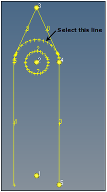
Figure 11. -
To exit the panels, click return twice.
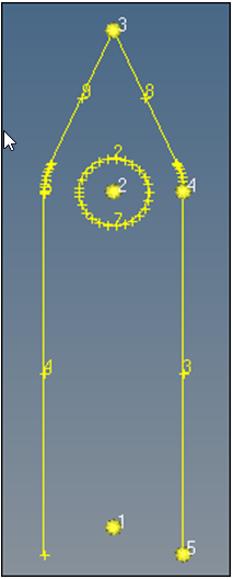
Figure 12.
Create a Component Collector
In this step you will create a component collector for surfaces.
- In the Model Browser, right-click and select from the context menu.
- In the Create Component dialog, type surfaces in the Name field.
- Click the Color icon and select purple.
- Click Create.
Create a Surface Square
In this step you will create a surface square on an X-Y plane.
-
To exit the panel, click return.
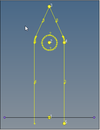
Figure 13.
Connect Parallel Lines
In this step you will create a line that connects two parallel lines on an X-Y plane.
-
Select the two straight lines that are perpendicular to the X-Y plane indicated
in the following image.
HyperMesh displays a bold, white line in the graphics area to represent the results.
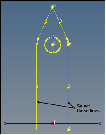
Figure 14.
Switch Current Work Component Surfaces
In this step you will switch the current working component surfaces to geometry.
Extend a Line
In this step you will extend a line to a surface edge.
-
On the Standard Views toolbar, click .
-
Select the lower-right edge of the purple indicated in the following
image.
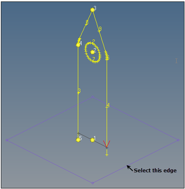
Figure 15. -
To exit the panel, click return.
Your model should resemble the following image.
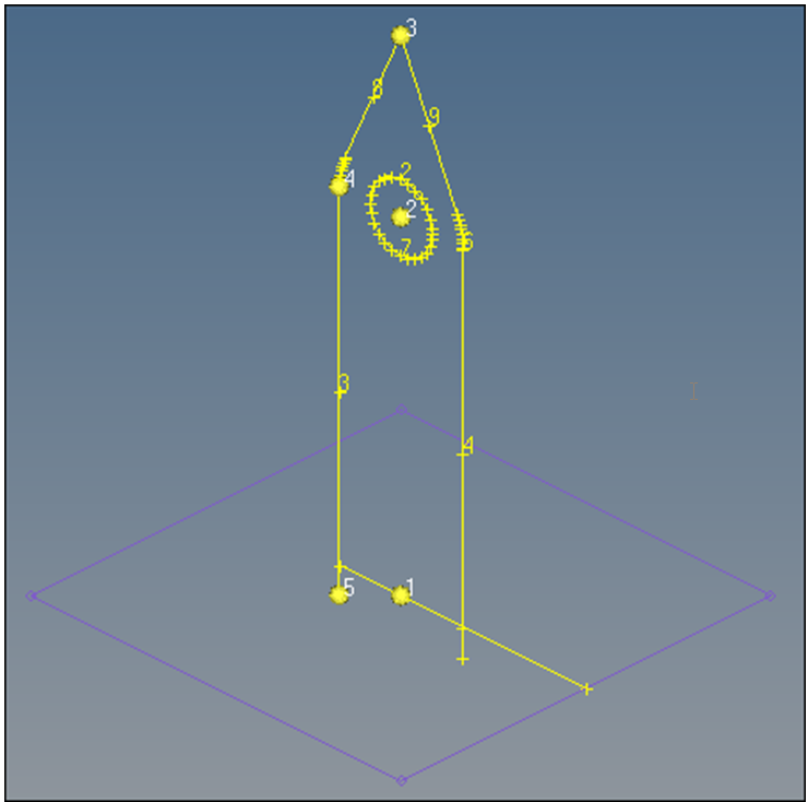
Figure 16.
Create a Fillet between Two Lines
In this step you will create a fillet between two lines.
-
Select the vertical line through which the extended line passes indicated in
the following image.
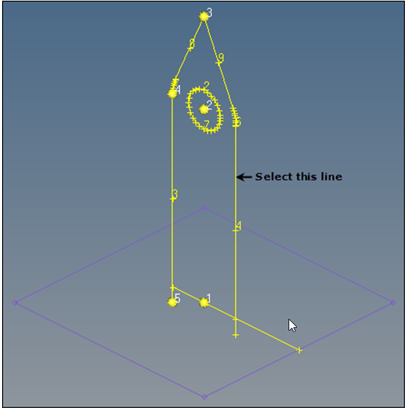
Figure 17. -
Select the top, right X for the fillet quadrant indicated in the following
image.
HyperMesh creates a fillet.
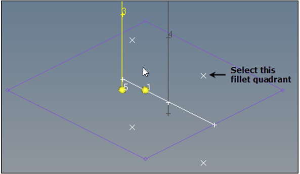
Figure 18. -
To return to the Lines panel, click return.
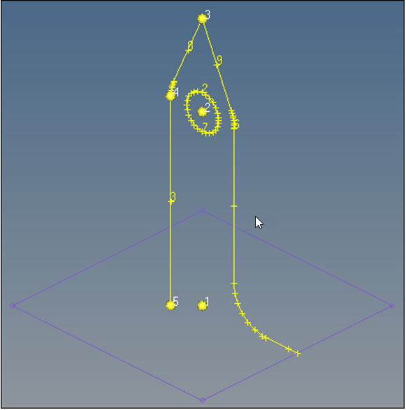
Figure 19.
Trim a Line by Plane
In this step you will trim a line by plane and delete a redundant line segment.
-
Select the vertical line that does not have a fillet indicated in the following
image.
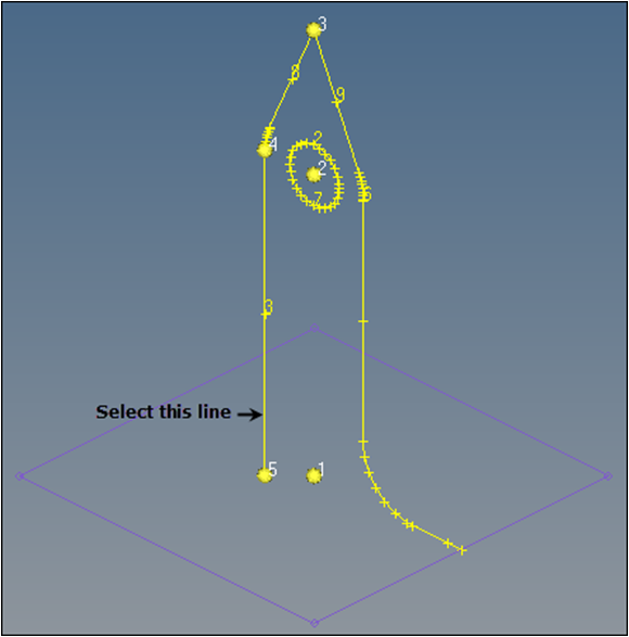
Figure 20. -
Select the small line segment under the X-Y plane.
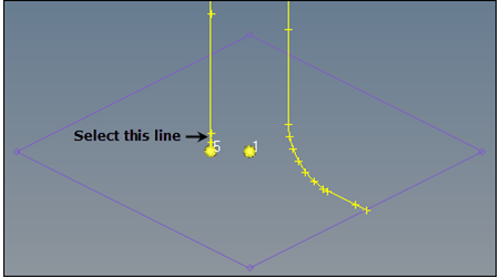
Figure 21.
Remove Temp Nodes
In this step you will remove all temp nodes.
Change the Rendering Mode
In this step you will change the rendering mode.
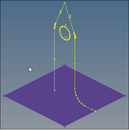
Figure 22.
Export Geometry to an IGES File
In this step you will export all geometry as an IGES file.