HM-2060: Create and Edit Solid Geometry
The use of solid geometry is helpful when dividing a part into multiple volumes, for example, to divide a part into simple, mappable regions for hex meshing.
In this tutorial, you will learn what solid geometry and topology is, and what 3D topology looks like.
- Point: 0 dimensional; has only x, y, and z coordinates
- Line: one-dimensional; has length, can be curved through three-dimensional space
- Surface: two-dimensional; has an area
- Solid: three-dimensional; has a volume
This exercise uses the solid_geom.hm file, which can be found in the hm.zip file. Copy the file from this directory to your working directory.
Open the Model File
In this step you will open the model file, solid_geom.hm.
-
In the Open Model dialog, open the
solid_geom.hm model file.
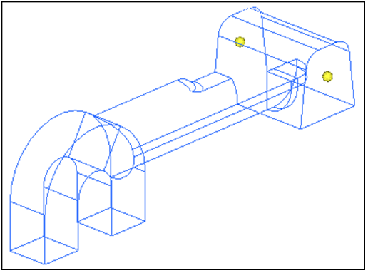
Figure 1.
Create Solid Geometry from Bounding Surfaces
In this step you will create solid geometry from the bounding surfaces.
Create a Solid Geometry Cylinder
In this step you will create a solid geometry cylinder using primitives.
-
Click bottom center and then select one of the temporary
nodes as illustrated in the following image.
The cursor advances to the normal vector selector.
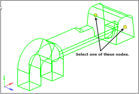
Figure 2.
Subtract a Cylinder's Volume
In this step you will subtract the cylinder's volume from the rest of the part.
-
To confirm the material has been removed, click
 on
the Visualization toolbar and rotate the model to inspect the part.
on
the Visualization toolbar and rotate the model to inspect the part.
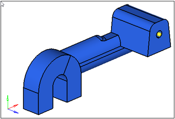
Figure 3.
Split the Solid Geometry
In this step you will split the solid geometry using bounding lines.
-
Select the four lines indicated in the following image.
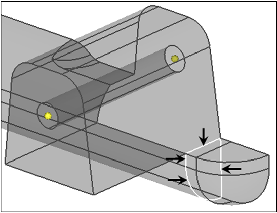
Figure 4. -
Click trim.
HyperMesh trims a plane.Note: The two solids now intersect.
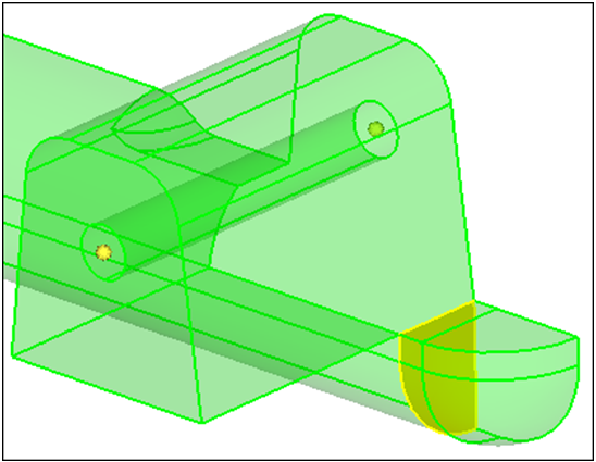
Figure 5.
Split the Solid Geometry Using a Cut Line
In this step you will split the solid geometry using a cut line.
You should still be in the Solid Edit panel, trim with lines subpanel.
-
Select the small, tetrahedral shaped solid created in Step 5.
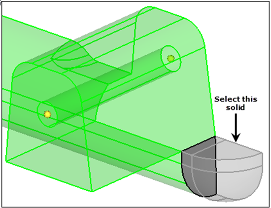
Figure 6. -
To define the end points of a line that roughly divides the tetrahedral solid
in half, select the two locations indicated in the following image.
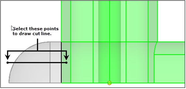
Figure 7. -
Select the half of the original tetrahedral solid indicated in the following
image.
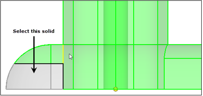
Figure 8. -
To split the solid indicated in the following image, repeat Steps 4 through
6.
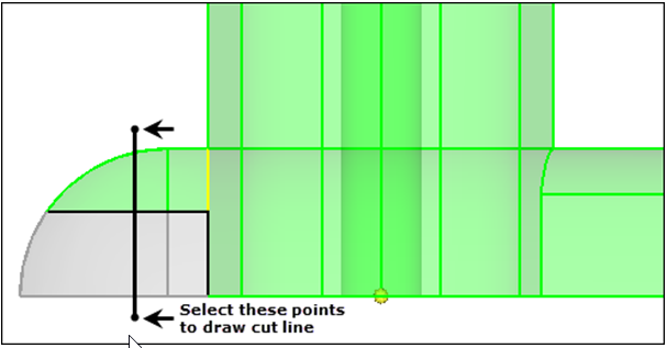
Figure 9. -
Select the solid indicated in the following image.
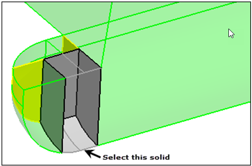
Figure 10. -
To split the solid indicated in the following image, repeat Steps 4 through
6.
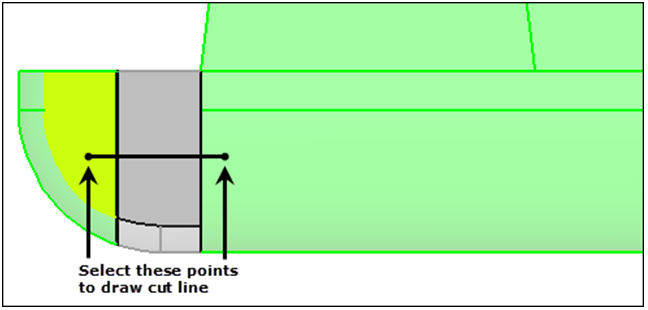
Figure 11.
Merge Solids
In this step you will merge solids together.
You should still be in the Solid Edit panel.
-
Select the three solids indicated in the following image.
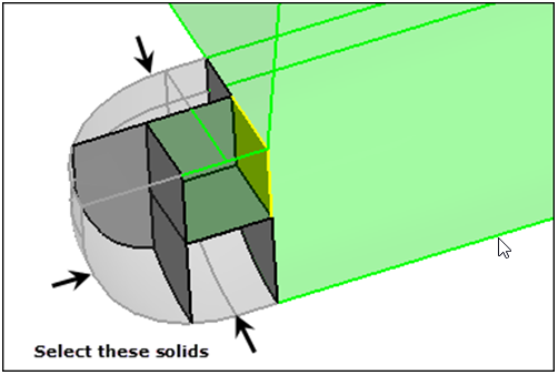
Figure 12. -
Click merge.
HyperMesh merges the solids.Note: The resulting solids in the tetrahedral area should resemble the following image. There should be two solid entities, with one of them being hexahedral in shape in the corner.
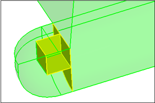
Figure 13.
Split Solid Geometry with a Plane
In this step you will split solid geometry with a user-defined plane.
You should still be in the Solid Edit panel.
-
Select the large solid representing the majority of the part as in the
following image.
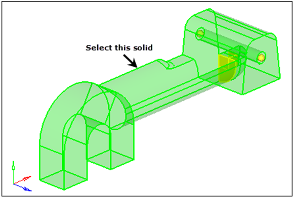
Figure 14. -
With N1 active, press and hold your left mouse button and move the mouse cursor
over one of the edges indicated in the following image.
HyperMesh highlights the edge.

Figure 15. -
Release the mouse button and select two nodes along its length.
Note: Your selection should look similar to the following image.
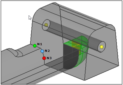
Figure 16. -
Click trim.
HyperMesh trims the solid.
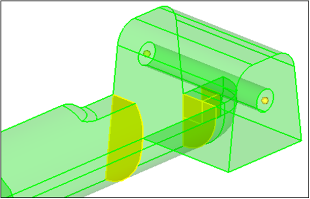
Figure 17.
Split Solid Geometry with a Swept Line
In this step you will split the solid geometry with a swept line.
You should still be in the Solid Edit panel.
-
Select the solid with the cylinder removed.
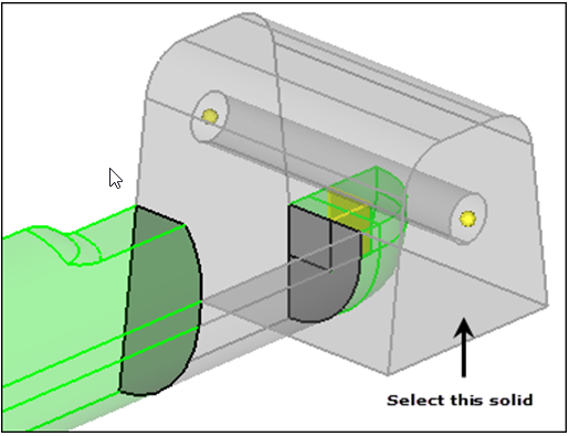
Figure 18. -
Select the edges indicated in the following image.
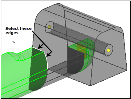
Figure 19.
Split Solid Geometry with a Principal Plane
In this step you will split the solid geometry with a principal plane.
You should still be in the Solid Edit panel.
-
Press and hold your left mouse button, and move the mouse cursor over the edge
indicated in the following image.
HyperMesh highlights the edge.
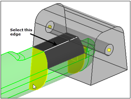
Figure 20. -
Release the mouse button, and left-click anywhere along the edge.
A purple temp node appears at the location to indicate the selection for the base node.
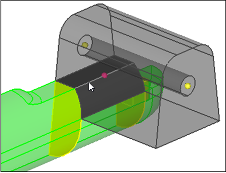
Figure 21. -
Click trim.
HyperMesh trims the solid.
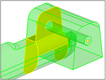
Figure 22.
Split Solid Geometry by Creating Surfaces
In this step you will split the solid geometry by creating surfaces inside the solids.
-
Select the five lines indicated in the following image.
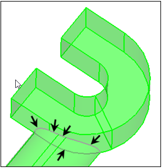
Figure 23. -
Select the four lines indicated in the following image.
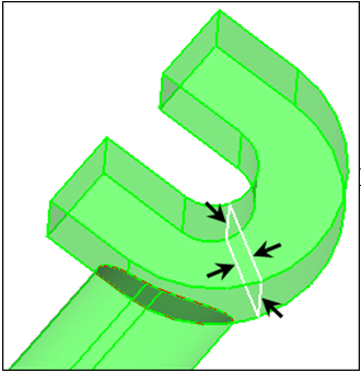
Figure 24.
Suppress Extraneous Edges
In this step you will suppress extraneous edges on the part.
-
Select the three solids indicated in the following image.
Note: To view a more efficient graphical representation of the solids, set the surface display mode to
 .
.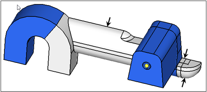
Figure 25.