HM-2020: Generate a Midsurface
In this tutorial you will generate a midsurface.
- Create a midsurface
- Visualize the midsurface by using shading options and transparency
This exercise uses CAD geometry data for a thin solid clip. Because of the small thickness of the part, it is assumed that it will be modeled for FEA as shell elements. The elements will be created on the mid-plane of the part.
In this exercise you will use the clip_midsurface.hm model file, which can be found in the hm.zip file. Copy the file from this directory to your working directory.
The surfaces in this model have no connectivity errors. This could be because the file was imported without errors or because the errors were corrected using HyperMesh. In this case, errors in the topology were repaired in the previous exercise (missing surfaces are re-created, duplicate surfaces are deleted, gaps are closed, and so on). For this tutorial, you can continue using the model you created in the previous tutorial, or you can open the new, clip_midsurface.hm, file. Either way, the geometry is at the point where you can use the Midsurface panel to generate a midsurface.
Open the Model File
In this step you will open and view the model file.
-
On the Visualization toolbar, click
 to
shade the model's geometry and surface edges, and click
to
shade the model's geometry and surface edges, and click  to change the geometry color mode to mixed. The
surfaces displayed in the graphics area represent a solid part.
Note: These visualization techniques will be necessary for viewing the newly created midsurface.
to change the geometry color mode to mixed. The
surfaces displayed in the graphics area represent a solid part.
Note: These visualization techniques will be necessary for viewing the newly created midsurface.
Generate a Midsurface
In this step you will generate a midsurface from the midsurface panel.
Review the Midsurface
In this step you will review the part's midsurface.
-
In the Model Browser, only display the Middle Surface
component. The graphics area displays the midsurfaces generated for the solid
sections of the model using the auto-midsurface panel.
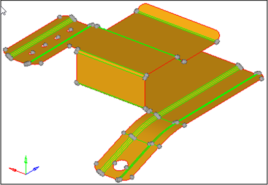
Figure 1. -
To open the Transparency panel, click
 on the Visualization toolbar.
-
Under transparency, click
 several times.
The surfaces in the lvl10 component become more and more transparent.
several times.
The surfaces in the lvl10 component become more and more transparent. -
To visualize the midsurface, rotate, zoom, and pan.
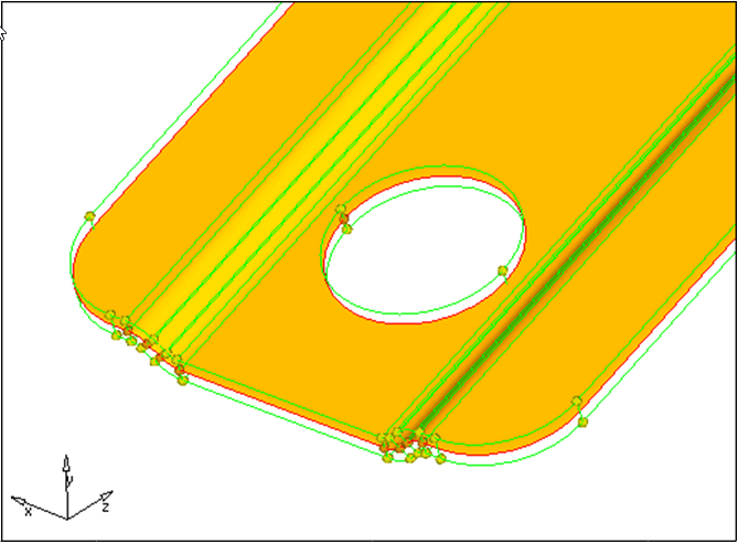
Figure 2.
Save Your Work
In this optional step you will save your work.
Now that the midsurface has been created, it is a good time to save the model.
You have now created surfaces on the mid-plane of the part. These surfaces can now be meshed or further modifications can be made to their topology, depending on the requirements of the analysis.