HM-2030: Simplify Geometry
In this tutorial you will change the shape of parts and simplify geometry.
This exercise involves changing the shape of a part in order to simplify the geometry. Certain details of the shape, such as small holes or blends, may simply not be necessary for the analysis being performed. When these details are removed, the analysis can run more efficiently. Additionally, mesh quality is often improved as well. Changing the geometry to match the desired shape can also allow a mesh to be created more quickly.
- Mesh the clip, review the mesh quality, and determine the features to be simplified
- Remove surface fillets
- Remove edge fillets
- Remove pinholes
This exercise uses the clip_defeature.hm file, which can be found in the hm.zip file. Copy the file from this directory to your working directory. This model file contains geometry that has been midsurfaced. Surfaces have been created on the mid-plane of the part.
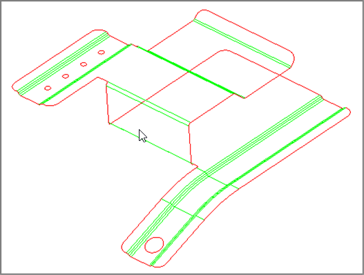
Figure 1.
Open the Model File
In this step you will open the model file.
- From the menu bar, click .
- In the Open Model dialog, open the clip_defeature.hm model file.
Turn Off the Display
In this step you will turn off the display of the lvl10 component.
If the lvl10 component is displayed, it needs to be turned off so that you can easily work on the midsurface geometry.
Mesh the Clip
In this step you will mesh the clip to view mesh quality before defeaturing.
-
To shade the model's geometry and surface edges, click
 on
the Visualization toolbar.
on
the Visualization toolbar.
-
Click mesh.
HyperMesh generates the mesh preview.
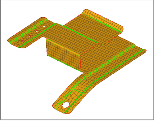
Figure 2.
Review Mesh Quality
In this optional step you will review the quality of the mesh that was created.
This step is optional. Pay attention to the areas that have an irregular, poor quality mesh. An irregular, poor quality mesh generally contains rows and columns of quads that are not neat. You will use the Check Elements panel to evaluate the minimum length check of the elements.
-
To evaluate the minimum length, click length. Many of
the elements that failed the length test are located around the fillets of this
model.
Note: For better visualization of element quality, you may need to display the geometry in wire frame mode by clicking
 on the Visualization toolbar.
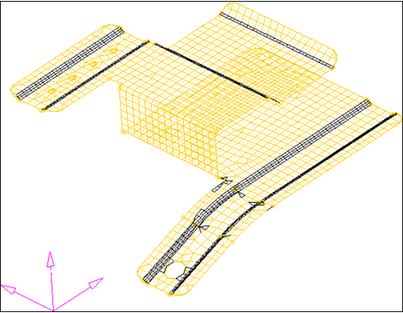
Figure 3.
Remove Pinholes
In this step you will remove four small pinholes.
Pinholes are closed free edge loops within a surface. Pinholes do not need to be circular.
-
Click find.
HyperMesh identifies all of the pinholes that have a diameter of 3 or less in the model and places a white xP symbol in their centers.
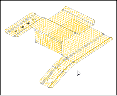
Figure 4.
Remove Surface Fillets
In this step you will remove all surface fillets in the clip.
-
If the model's geometry and surface edges are not shaded, click on
the Visualization toolbar.
-
Click find.
HyperMesh identifies all the surface fillets with a radius of 2 or greater in the model.
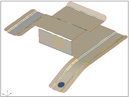
Figure 5.
Identify and Remove Rounded Corners
In this step you will automatically identify and remove rounded corners of surfaces.
You should still be in the Defeature panel.
Save Your Work
In this optional step you will save your work.
Now that the model has been simplified, it is a good time to save the model.
The model is now represented in a much simpler form that suits the analysis that will be performed. Holes, surface fillets, and edge fillets were removed that were considered too small to be captured by the desired element size of 2.5.