Use linear symmetry to apply morphs to the model in such a way that the model is
essentially reduced to two dimensions.
From the Tools page, click HyperMorph.
Click Systems.
Create a system with the x-axis pointing along the dimension to be
reduced.
Click return to go to the HyperMorph module.
Click Symmetry.
Select the create subpanel.
In the name field, enter a name.
Select the global domain icon.
Switch the selector from 1 plane to linear.
Select the system you created.
Select x-axis as the axis to align the symmetry.
Click create.
A linear symmetry is created along the x-axis of the system. The icon for a linear
symmetry consists of two parallel lines along the dimension to be reduced. The
origin of the system is irrelevant. Now each handle acts on the mesh as if it were a
line extending along the system x-axis. If two handles lie along a line parallel to
the system x-axis, they will be linked through symmetry. When you move a handle, all
the nodes and handles with the same y and z coordinates will move along with
it.
Note: Since linear is a non-reflective type of symmetry, leaving symlinks
unchecked will not prevent the handles from having linear influences. However,
it will stop movements from one handle from being applied to others that are
linked via the symmetry. If you wish to turn the symmetry off for a given
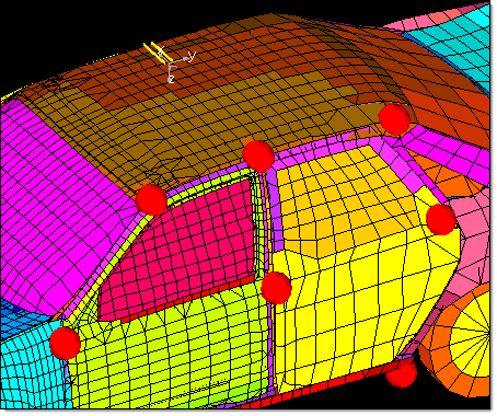
morphing operation, make the symmetry inactive in the Morph Options panel. Figure 1. System and Linear Symmetry. The linear symmetry icon consists of two parallel lines along the
system x-axis. Note that the placement of a linear symmetry system does
not matter, the effect of the linear symmetry system is determined only
by the direction of the x-axis.
Applying a linear symmetry is very useful for making profile changes to
a space frame model. It does not matter where the handles are placed along
the x-axis, greatly simplifying the model set up. You only need to look at
the model from one view to set up the handles and to morph the model. For
models with a large number of elements this can save a great deal of
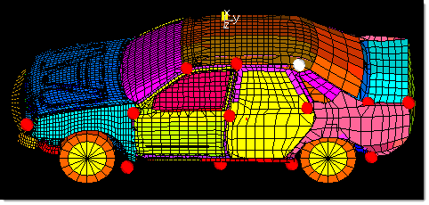
time. Figure 2. Using Linear Symmetry. The handle on the rear part of the roof is selected and the entire
rear portion of the roof is morphed along with it. With linear
symmetry you only need to place handles on one side of the model to
affect the entire profile.