Visualization
Visualization of commonly used coordinate systems.
Orientation Review
Plot and modify common coordinate systems used in CAE analysis.
The Orientation Review tool provides visualization of commonly used coordinate systems. Additionally, there are several methods to manipulate the orientation of certain coordinate systems.
| Tab | Functionality |
|---|---|
| Element System | Plot the default local system for 1D, 2D or 3D elements. |
| Nodal System | Plot systems associated with nodes. Typically used to review displacement and reference systems in the OptiStruct and Nastran user profiles. |
| Orientation | Plot and manipulate the order of nodes, sets default element coordinate systems. |
| Material System | Plot the material coordinate system on elements. |
| Ply Directions | Plot the 1, 2 and/or 3 directions of plies. |
| Ply Normals | Plot and correct the ply normal of plies. |
Elemental System
Plot the default element coordinate system for 1D, 2D, or 3D elements.
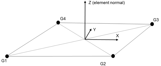
Figure 1.
| Option | Action |
|---|---|
| Pick Elements | Select elements on which to plot x, y, and/or z element system directions. |
Elemental System Usage
How to use the Elemental System tab.
-
Select one of the following:
- Apply - Show the system display
- Clear - Clear the plot generated by this tab
- Clear All - Clear all plots generated by Orientation Review
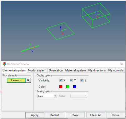
Figure 2.
Nodal System
Plot systems associated with nodes.
Typically used to review displacement and reference systems in the OptiStruct and Nastran user profiles.
| Option | Action |
|---|---|
| Pick Nodes | Select nodes on which to display system information. |
| System | Determines system type to plot. Specific to OptiStruct and Nastran displacement and reference
systems on GRID card. Choose from:
|
Nodal System Usage
How to use the Nodal System tab.
-
Select one of the following:
- Apply - Display the displacement system assigned to each selected node
- Clear - Clear the plot generated by this tab
- Clear All - Clear all plots generated by Orientation Review
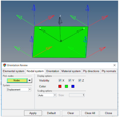
Figure 3.
Element Orientation
Plot and manipulate the order of nodes that sets default element coordinate systems.
Element orientations for most solvers are determined by the sequence of nodes on the element card. This tab provides several methods of node renumbering to change element coordinate system x or z axis.
| Option | Action |
|---|---|
| Pick Elements | Select the elements on which to manipulate node numbering. |
| Function | This provides several methods of reviewing elemental system
directions and changing node ordering. Choose from:
|
| Align N1-N2 dir. Methods | Set the N1-N2 direction of selected elements as close as
possible to the input method, without remeshing. The tool will
not change the element normal. Intended for legacy OptiStruct and Nastran use cases. In typical cases, use
material orientation methods to set material directions. The
following methods are available:
|
Orientation Usage – Reverse 1D
How to use the Orientation tab.
-
Select one of the following:
- Apply - Reverse selected 1D element directions
- Clear - Clear the plot generated by this tab
- Clear All - Clear all plots generated by Orientation Review
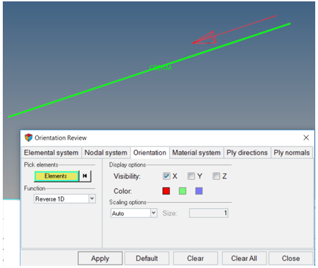
Figure 4.
Orientation Usage - Align N1-N2 Direction
How to use the Orientation tab.
-
Select one of the following:
- Apply - Align N1-N2 directions
- Clear - Clear the plot generated by this tab
- Clear All - Clear all plots generated by Orientation Review
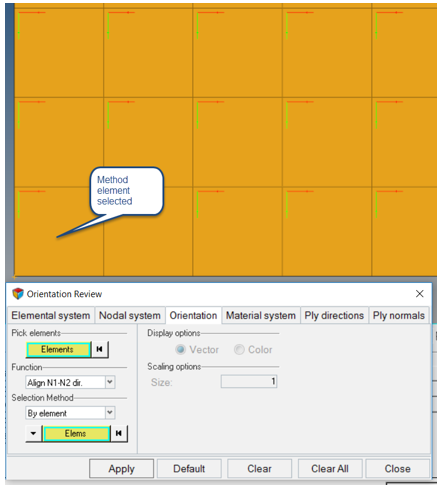
Figure 5.
Material System
Plot the material coordinate system on elements.
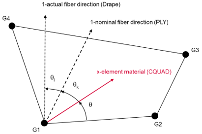
Figure 6.
| Option | Action |
|---|---|
| Pick Elements | Select elements on which to plot x, y and/or z material system directions. |
Material System Usage
How to use the Material System tab.
-
Select one of the following:
- Apply - Show the system display
- Clear - Clear the plot generated by this tab
- Clear All - Clear all plots generated by Orientation Review
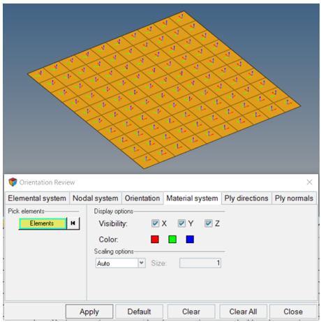
Figure 7.
Ply Directions
Plot the 1, 2 and/or 3 directions of plies.
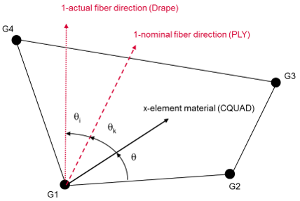
Figure 8.
| Option | Action |
|---|---|
| Select ply | Select a ply to plot orientation by clicking the yellow ply collector. Alternatively, use the arrows to move through the list of plies in the model. |
| Options | Choose which ply directions to plot:
|
Ply Directions Usage
How to use the Ply Directions tab.
-
Select one of the following:
- Apply - Show the ply
directions for the selected ply
Use the arrows in the ply selection to toggle through plies in the model.
- Clear - Clear the plot generated by this tab
- Clear All - Clear all plots generated by Orientation Review
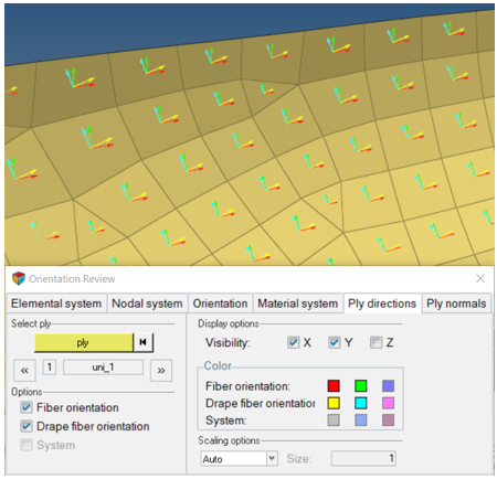
Figure 9. - Apply - Show the ply
directions for the selected ply
Ply Normals
Plot and correct the ply normal of plies.
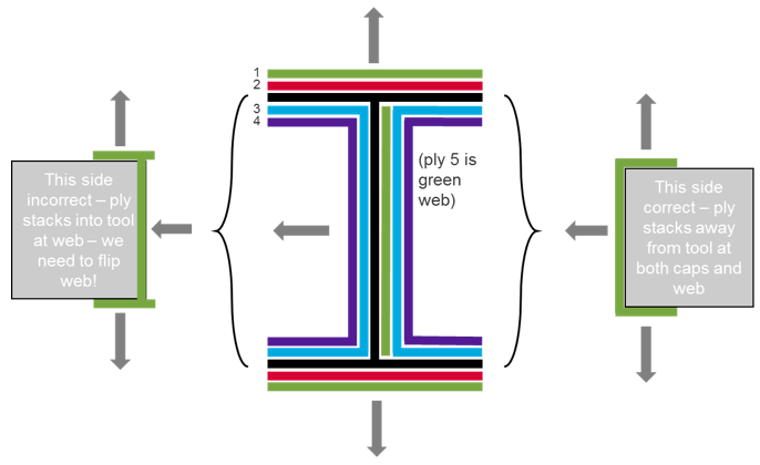
Figure 10.
The discontinuity in stacking direction on the left side of the I-beam model will be corrected using ply normals. Ply normals manipulate the direction an individual ply stacks. When the ply normal tool is used to reverse a ply normal, a drape table is created for the ply. It subtracts 2*θ from the ply orientation which is mathematically equivalent to flipping the direction the ply is stacked.
| Option | Action |
|---|---|
| Select ply | Select a ply to plot orientation by clicking the yellow ply collector. Alternatively, use the arrows to move through the list of plies in the model. |
| Normals | Choose from:
|
| Pick elements | Typically only a portion of a given ply requires that ply normals are flipped. This selection determines which elements of a ply will be flipped. |
Ply Normals Usage
How to use the Ply Normals tab.
2D Detailed Thickness and Layers
Visualization toolbar options for elements and plies.
Element and Ply Visualization
The exact visualization of ply layers in a composite material requires the use of both the Composite Visualization and Element (complexity) Visualization options.
These options work in tandem to determine exactly how composite layers will display in HyperMesh.
 (1D/2D
Element Representation)
(1D/2D
Element Representation) (Composite
Visualization)
(Composite
Visualization)
- 2D Traditional Element Representation (
 )
) - HyperMesh represents composite layers, when visible,
as 2D shells:
Figure 11. Layers Off
Figure 12. Composite Layers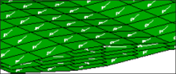
Figure 13. Layers with Fiber Direction - 2D Detailed Element Representation (
 )
) -
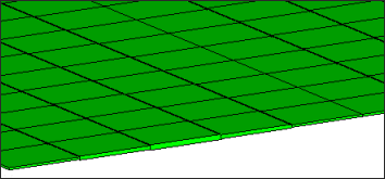
Figure 14. Layers Off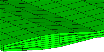
Figure 15. Composite Layers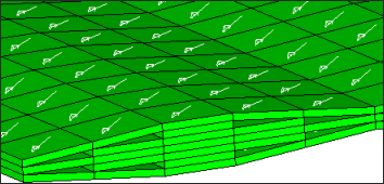
Figure 16. Layers with Fiber Direction - 2D Traditional and Detailed Element
Representation (
 )
) -
Figure 17. Layers Off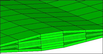
Figure 18. Composite Layers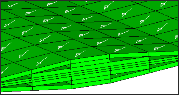
Figure 19. Layers with Fiber Direction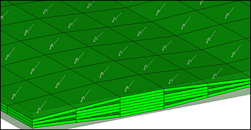
Figure 20. Layers with Fiber Direction for Continuum Shells. Original element geometry is shown in transparent mode, so that differences in elemental versus property thickness can be easily seen.