Composites Panel

Use the Composites panel to assign and review the element material orientation of a mesh of shell and continuum shell elements, or to review the fiber direction (ply angle) of individual composite layers.

Element Normals Subpanel

Use the Element Normals subpanel to review, adjust, or reverse element normals.

The normal direction of elements is essential for the stacking direction of plies.
Option Action
entity selector
Select elements to display, adjust, or reverse the normals.
displayed 2D elems (default)
Automatically select displayed 2D elements.
comps
Select components that contain elements for inclusion.
elems
Select elements directly.
When elems is selected, choose a selection mode.
elems
Select individual elements, or select all of the elements contained by a component or on a surface.


Figure 1. Example: Elems Selection
2D faces
Select all of the elements on a 2D face.
If there are discontinuities on a face, then only the elements in-between the discontinuities will be selected.


Figure 2. Example: 2D Faces Selection
2D faces ext
Select all of the elements on a 2D face that contain discontinuities.


Figure 3. Example: 2D Faces Ext Selection
orientation
Select how bars are oriented in 3D space.
Vector
Use the standard plane and vector selector to determine the orientation of the bar.
Select three points to define a plane whose normal serves as the vector using the N1 N2 N3 selectors.
Specify a global axes by selecting x axis, y axis, z axis.
Specify a desired vector by selecting vector.
Components
Determine the bar's orientation relative to how the bar element's coordinate system is defined.
Orientation in basic
Use the default system of the grid points that define the element.
Orientation in displacement
Applies only if the referenced grid points have a displacement system defined.
Specify the direction of the local y axis of the bar by entering the X, Y, and Z components.
Node
Select a node to specify the vector orientation using the direction node selector.
Plane
Make the vector parallel to a plane based on the global coordinate axes.
Select a combination of the global coordinate axes that describe the plane you wish the bar to be parallel to.
use feature angle Enter a feature angle (mode=4, and a feature_angle is used). For each connected section, the normals are adjusted for all elements in that section to be consistent with the 'dominant normal direction' already existing within that section, with the sections defined based on the specified feature angle. Clear this checkbox to set the mode=0, and not use a feature_angle.
vector display normals / color display normals
Select a method to review normals of elements.
vector display normals
Show normals as vectors.
Specify a vector size in the size= field. If a value greater than zero is specified it shows the normal in that size based on model units. Otherwise, the vector size is equivalent to the smallest size of the element.
color display normals
Show normals by color mode.
Red indicates the positive normal direction, while blue indicates the negative direction.
display adjusted only Display the normals which have been changed when you click adjust.
display Display the normals of selected elements or surfaces as vectors or in color mode.
adjust Adjust normals based on the selected orientation method.
reverse Flip all normals of selected elements or surfaces.
face angle / individual selection
face angle
Angle between the normal of facets that share an element edge. A facet can either be a shell element itself, or one of the faces of a solid element. The normal of triangular facets is that of the plane defined three corner vertices. Whereas, the normal of quadrilateral facets is calculated by taking the cross-product between its two diagonals. This special treatment for quadrilaterals is because a warped shape does not lie completely on a plane.
individual selection
Select individual elements on a face or select individual free/shared edges of elements.

Material Orientation Subpanel

Use the Material Orientation subpanel to assign systems to elements or properties.

If you change a system after assignment it will only affect the material orientation if by system id has been used. In all other cases the angle calculated at the time of assignment will not be updated. To update the angle in those cases, reassign the system to the elements.

In Abaqus, by system axis is the only option available. Systems will be assigned to the properties selected. In case the system has no ORIENTATION attribute, it will be set and a generic name will be given. The appropriate axis of rotation will be set automatically in the card image.

After assignment the material orientation will be shown with drawn vectors. The size can be adjusted in the panel based on model units. The join lines option can be set in case you want to see connected lines instead of the vector review. The color of the vectors or lines can be changed in this panel using the color selector.

Review of material orientations is possible as well. If no orientation is assigned, the default orientation will be shown.
Option Action
entity selector Select elements or properties for material orientation assignment.
Note:
  • OptiStruct or Nastran: Material orientation is assigned to the elements.
  • Abaqus: A property needs to be selected for material system assignment. A system to element assignment is currently not possible.
rebar layer Supports system assignment to the *REBAR LAYER card for modeling reinforcement.

If the checkbox is selected, the REBAR LAYER attribute and a system reference are assigned to SHELL SECTION (homogeneous and composite), MEMBRANE SECTION and SURFACE SECTION.

Upon assignment the REBAR LAYER attribute will be set in these properties. Orientations for these properties can as well be reviewed in this panel if the flag is set.
Note: Only available in the Abaqus solver interface.
material orientation method With the by system id method a system is assigned to the elements, but in all other methods an angle is relative to nodes 1 and 2. An exception is the Abaqus solver interface, where a system is assigned by system axis to the property made in the panels selection.
by system id
Assign the ID of a coordinate system to selected elements.
Activate the system selector to select a system from the modeling window, or double-click the system selector to enter a system ID.
by system axis
Specify the axis of a selected system to project (local 1-, 2- or 3-axis).
by vector
Specify the material orientation by directly entering the desired material angle using the by angle option, selecting one of the global axes, selecting an existing vector entity, or by selecting two or three nodes (N1, N2, N3 selector).
Two nodes specify a vector along the selected nodes. Three nodes specify a vector perpendicular to the plane built by the selected nodes using the right hand rule.
by angle
Specify the angle of the material orientation. The material direction is the direction from node 1 to 2 of the element, rotated by this angle.
size= Enter a value in model units that specifies the length of the vectors for reviewing the material orientation.
join lines Connect lines instead of vectors.
color Select a color to assign vectors or lines for review.
assign Assign a material system to the selected elements or properties. Either a system reference will be made, or the selected system axis or the vector will be projected onto the element surface. After performing this operation, the material orientation will be highlighted by either vectors or lines.
reset Reset the material orientation review.
review Select elements or properties for which you want to see the material orientation.

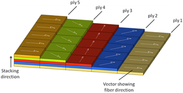
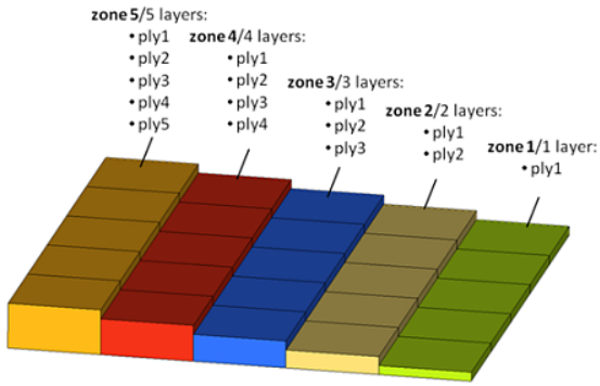
Ply Directions Subpanel

Use the Ply Directions subpanel to review the fiber direction of individual layers.
Option Action
entity selector Select elements or properties to review ply directions.
rebar layer Review the rebar orientation angle for each individual layer, in cases where the GEOMETRY=CONSTANT type is used.
Note: Only available in the Abaqus solver interface.
review methods
ply based model
Review the fiber directions for an entire ply definition.
This option requires that the model has been defined in terms of plies (not all solvers support ply-based modeling) or using HyperMesh ply and laminate entities. Click ply = to select a ply from to review. The fiber direction of the elements associated with the selected ply will be shown.
A ply based model consist of multiple plies representing the layers building a laminate. A stacking sequence needs to be defined to specify the order of how those layers are stacked. The big advantage of this type of modeling is that plies can span across elements. The modeling comes close to the way composites are manufactured.


Figure 4. Ply Based Model
zone based model
Select elements or properties, then enter the layer number to review.
This option requires that each group of elements (zone) with the same number of layers have its own property definition.
This review method works for either zone- or ply- based models.
global zone based model
Review a model defined using global ply names or ids, for example ply name in Abaqus or global ply identification number in OptiStruct.
Select elements or properties, then click ply= to find all of the ply names or ids which are referenced by your selection. Select a ply to review the fiber direction.
Ply ids or names are repeated in several property definitions, to highlight that these layers extend across two or more zones.
Figure 5. Global Zone Based Model. Each zone requires its own property, but the name ply1 spans across all zones.


size Specify a value in model units that specifies the length of the vectors for reviewing ply directions.

This only affects visualization, not any calculations.

join lines Connect lines instead of vectors.
color Select a color to assign vectors or lines for review.
review Review ply directions.

Select elements or properties and ply= when dealing with a zone based or a global zone based model.

For a ply based model you only need to select the ply of interest by clicking ply=.

reset Clear the ply direction review visualization vectors or lines.