Aerospace Composite Tools
Aerospace tools for working with composites.
PCOMP From CSV
PCOMP from CSV generates HyperMesh composite properties from data defined in a .csv file.
The required file format is shown in the table below. Layers of a property must share a single material ID and thickness. If this is not your use case, refer to Data I/O Spreadsheets for other options.
From the menu bar, click . In the Import file field, browse to the appropriate file and then click Create.
| PCOMP ID | Material ID | Thickness | Orientation | |||||||
|---|---|---|---|---|---|---|---|---|---|---|
| 1 | 1 | 0.01 | -45 | 0 | 45 | 90 | 90 | 45 | 0 | -45 |
| 2 | 1 | 0.01 | 0 | 90 | 0 | 90 | ||||
| 11 | 5 | 0.02 | 30 | 0 | 30 |
Ply Geometry Smoothing
Ply Geometry Smoothing provides functionality to smooth finite element ply shapes, usually generated from concept level composite freesize optimization, and to generate geometry from finite element ply shapes.
-
Provide the step file name.
Geometry plies are created and exported to step files.
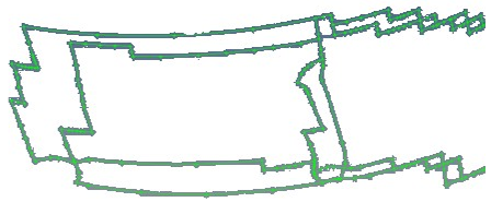
Figure 1. Result of Smoothing with Iterations = 0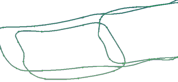
Figure 2. Result of Smoothing with Iterations = 20
Ply Auto Rename
Ply Auto Rename changes ply names so that the assigned material, thickness and angle are appended.
From the menu bar, click .
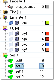
Figure 3. Ply Names as Defined in the CAD System
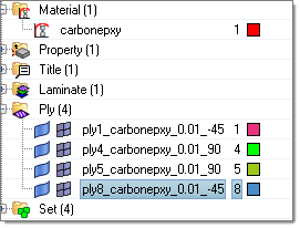
Figure 4. Updated Ply Names
FE Absorb Plies
FE Absorb Plies generates a ply-based model from zone-based properties.
Entities that are created are laminates, plies, and template properties.
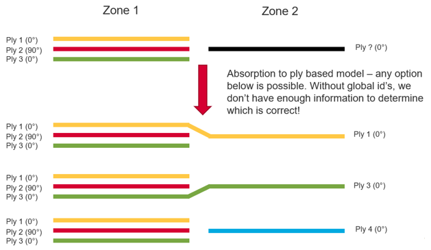
Figure 5.
-
Import zone-based models with zone-based solver properties.
These FE models do not have any plies or laminates. The goal is to create plies and laminates from the zone-based solver properties.
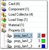
Figure 6. No Plies or Laminates are in the FE Model -
If a zone ply shape has multiple disconnected regions, generate multiple plies,
one for each disconnected region, by selecting Split disconnected ply
regions into separate new ply entities.
After the conversion, laminates and plies are created. However converting a zone-based model to a ply-based model is not deterministic if global IDs or names are not defined in the properties. Many possibilities exist, especially the laminate stacking order. You are advised to check the laminate and reorder, if necessary.
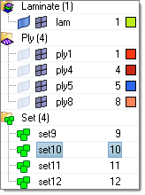
Figure 7. Ply, Laminate and PCOMPP are Created in the Model after FE Absorb
Material Orientation
The Material Orientation tool provides several methods of assigning material x directions for shell and solid elements, and additionally z directions for solid elements.
- Select the Entities on which to assign material orientation, either Elements or Properties.
- Set the Color of orientation vectors drawn after applying material orientation.
- To set the scale of orientation vectors drawn after applying material orientation, set Scaling Option to Auto or Manual.
- Type a value into the Size field for the manual input for size of orientation vectors drawn after applying material orientation.
- Set the X direction method. Choose from the following:
- Curve – spatially map input curve(s) as the x direction
- Lines/Edges – lines which define the orientation
- Flip direction – for lines/edges only. Determines whether the curve provided is +x direction or -x direction.
- Nodes – list of lines that define the orientation
- System ID – system assigned as orientation
- System Axis – system and axis of system to map as x direction
- Angle – for OptiStruct and Nastran only. Directly enter rotation applied on THETA field of element.
- Curve – spatially map input curve(s) as the x direction
- Set a value for Normal by choosing one of the
following:
- Element Normal – uses element z direction (can be viewed from panel if elements are selected). Typically, this option should be used.
- Surface Normal – aligns material z direction spatially to selected surface.
By Curve
- Select the elements for which a new material angle will be assigned.
- Select the lines or list of nodes to define the material direction. The
element centroid will be taken and projected to the closest line/node
segments and the line tangent direction will be found to assign the material
angle.
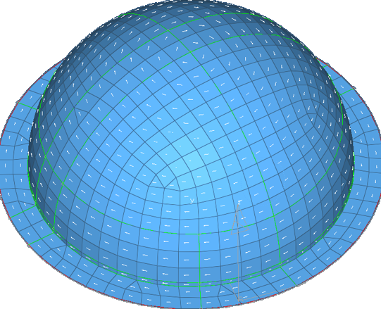
Figure 8. A Circular Pattern of the Material Orientation is Assigned Based on the Outer Circular Line Direction
Other material orientation tools are also available.
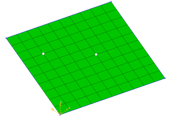
Figure 9. Two Nodes are Selected for Material Direction
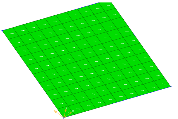
Figure 10. Material Direction in the Same Direction as two Nodes
By System ID
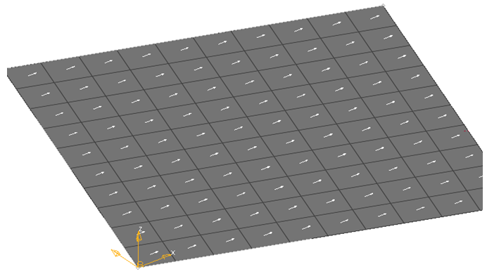
Figure 11. X Axis of the System is used for Projection
By System Axis
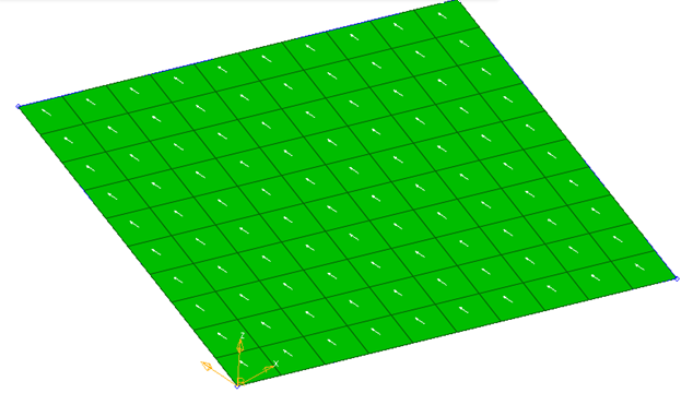
Figure 12. System Local Axis 2 is Projected to Create Material System
By Angle
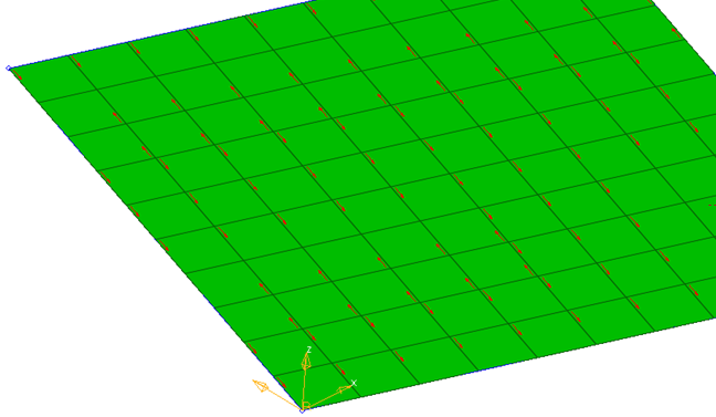
Figure 13. Element N1-N2 Direction
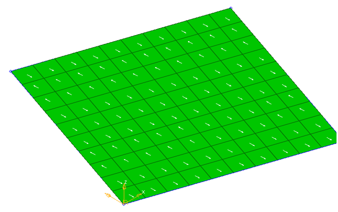
Figure 14. Material System is Created at an Angle to N1/N2 Direction
Shell To Solid Conversion
The Shell To Solid Conversion tool provides functionality to generate solid elements and material orientations from a ply based shell model.
-
Select Create Props to create solid composite properties
assigned to created solid elements.
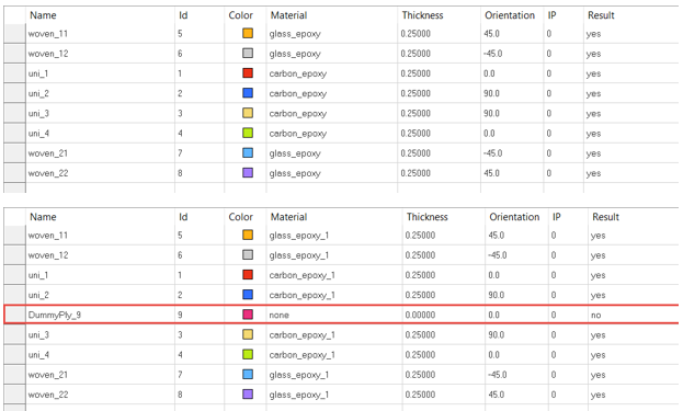
Figure 15.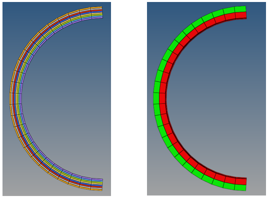
Figure 16. Dummy Ply for Create Multiple Solids Using Dummy Ply Separation