Pre-Tension Section

In the Pre-Tension Section dialog, define the *PRE-TENSION SECTION section and related assembly loads and constraints.

The Pre-Tension Section dialog contains the following buttons:
Table 1.
Button Action
OK Updates the Engineering Solutions database with the changes and closes the Pre-tension Section dialog.
Apply Updates the Engineering Solutions database with the changes without closing the Pre-tension Section dialog.
Cancel Closes the Pre-tension Section dialog without updates.

Pre-Tension Section: Define Tab

In the Define tab, define a pre-tension section on existing bolts.

These bolts can be modeled by beams, truss or solid elements. This tab offers an automatic and manual way of defining the pretension section. You can also create loads and constraints applied to the pretension node from this tab.

Pre-Tension Definition

When the pre-tension definition is modeled by truss or beam elements, use the Select button to pick the 1D element to which the pre-tension shall be applied. When the Auto generate pre-tension node option is on, a pretension node in the middle of the selected element will be created. The same node will be populated in the By Node ID field and will also receive an Engineering Solutions tag Pretension_Node_<node id>.

If Auto generate pre-tension node is not active while selecting the 1D element, you can select a pre-existing node or node set, or as an option, create a node set and select this node set to apply pre-tension load and boundary conditions on.
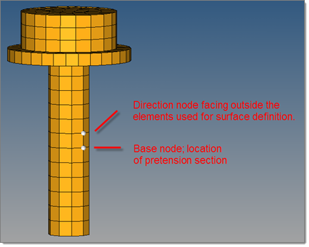
When modeling a bolt by solid elements, you can take advantage of some automation as well. In this case you need to select a surface. If the Auto generate surface and pre-tension node option is enabled (Text dependent on either Element or Surface option), the only thing to specify is a base and a direction node.


Figure 1.

The tool then creates a surface (*SURFACE) cutting through the bolt at the location of the base node. It also creates a node in the surface plane, outside the bolt and not attached to the model. This node automatically gets an HM tag HMpre-tension_node so that it is easier to find.

If you want to use existing surfaces, pre-tension nodes or node sets, you need to disable the automatic surface and node generation setting and assemble each part of the pre-tension section manually.

Assembly Load Definition

In the lower part of the dialog, you can directly apply a pre-tension load or constraint onto the pre-tension node (the node must exist). For the pre-tension load or constraint, a load collector named HMpre-tension_load or HMpre-tension_constraint is created or reused, if it already exists.

If you enable Fix assembly load, a second constraint is created in a load collector called HMpre-tension fix.

The assembly load/constraint definition part of the dialog can be used for both the manual and automatic process.

Pre-Tension Section: Parameter Tab

In the Parameter tab, define optional data lines for the *PRE-TENSION SECTION card.

Check Dataline to activate all three input boxes for the first, second, and third component of the normal.

Click Define by vector to define the values in the input boxes by a vector. To create a vector, click Create/Edit vector.
Note: The NSET parameter is currently only supported on the card image.