FBD Plot and Display
Define visualization options for the free-body plot.
- Free body forces/moments
- Defines whether free-body forces and moments must be shown at each boundary
node or at all nodes. If the section group is made up only by elements and
the node ID list is empty, the boundary nodes option searches for all of the
nodes that are shared with the rest of the model.
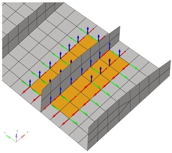
Figure 1. All Nodes Option
Figure 2. Boundary Nodes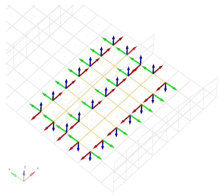
Figure 3. Boundary Nodes - Resultant forces/moments
- Defines that free-body forces and moments must be shown at the summation point that is defined. If more than one option is selected, forces and moments are summed up.
- Cross Section Position
- Moves the cross-section plane along its normal direction within the boundaries of the model. If the cross-section is realized, this option will not be available.
- Flip
- Allows you to select nodes that are on the opposite side of the
cross-section’s plane normal. If the cross-section is realized, this option
will not be available.
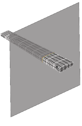
Figure 4.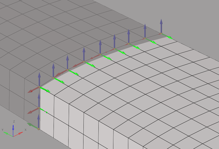
Figure 5.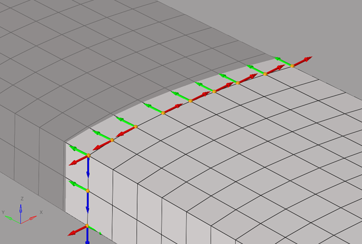
Figure 6. - Tables
- Creates tables with free-body forces and moments for one or multiple sections and for one or multiple loadcases. The summary table (and summary table summation points) can be used to create Potato/VMT plots.
- The summary table shows all forces and moments for nodes and summation
points.
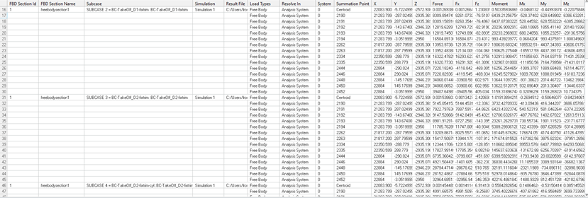
Figure 7. - The summary table summation points show all forces and moments at summation
points only.
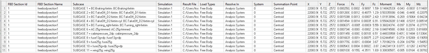
Figure 8. - The min/max table shows the higher and lower values of forces and moments at
summation points among the selected loadcases.
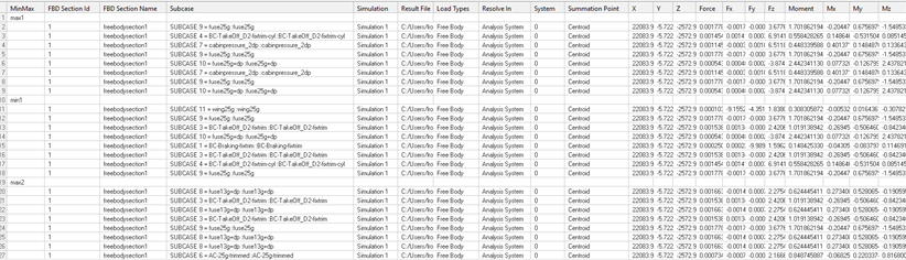
Figure 9. - Load Creation
- Creates an include file, where free-body forces and moments are properly realized as loads for that model for selected sections and selected loadcases.
- Resolve In
- Defines the coordinate system in which the loads will be created. Options vary depending on the solver.
- Include Name
- Defines the name of the include file in which the loads will be exported.
- Forces
- Selects force components to be exported.
- Moments
- Selects moment components to be exported.
- Create Fields
- Create field entities with free-body forces and moments for the selected sections and selected loadcases.
- Load Types
- Select what type of free-body data must be shown. Options vary depending on the solver. If more than one option is selected, values at the same location are summed up.
- Tolerance
- Forces or moments with an absolute value lower than the tolerance are not displayed.
- Forces
- Defines which force components will display.
- Moments
- Defines which moment components will display.
- Show Values
- Defines if free-body vector values will display.
- Size Scaling
- Defines how free-body vectors will be scaled for visualization.
- Arrow Length (%)
- Scales free-body vectors for visualization.
- Color
- Change the color of each force or moment component.
- Vector Heads
- Defines if the free-body vector points to the node or out of it.
- Vector Style
- Change the style of free-body vectors.
- Numeric Format
- Defines if free-body vector values should be displayed in fixed or scientific format. It also defines the amount of decimal places.