Near field Goal
Optimise the near fields that are solved as part of the Feko model.
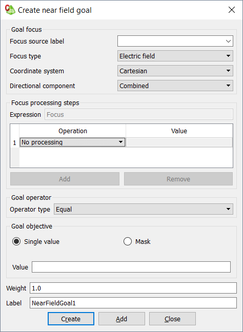
Figure 1. The Create near field goal dialog.
The Focus is identified based on the label of a Near fields request in CADFEKO or of an FE card in EDITFEKO.
The following focus types can be optimised:
- Electric field
- The electric field part of the near field is considered.
- Magnetic field
- The magnetic field part of the near field is considered.
- Electric flux density (normalised)
- The Electric flux density (normalised) considers the electric field scaled by the relative permittivity of the medium where the near field is calculated. These are normalised quantities, with the electric flux densities scaled by the permittivity of free space. The normalisation prevents the goal function from having values that are small enough for the optimiser to consider them to be zero.
- Magnetic flux density (normalised)
- The Magnetic flux density (normalised) considers the magnetic field scaled by the relative permeability of the medium where the near field is calculated. These are normalised quantities, with the magnetic flux densities scaled by the permeability of free space. The normalisation prevents the goal function from having values that are small enough for the optimiser to consider them to be zero.
Coordinate System
The coordinate system in which the directional component of the near field is required must be selected. The available coordinate systems are Cartesian, Cylindrical(X)/(Y)/(Z), Spherical and Conical. This coordinate system selection defines the options available in the Directional component drop-down list.
Directional Component
The options available in the Directional component drop-down list depends on the choice of Coordinate system, but are independent of the near field request sampling point positions.
- Radial or X/Y/Z/Phi/Theta-directed
- In the chosen Coordinate system, the field in any of the 3 coordinate directions may be requested. Each individual component of the electric or magnetic near field is a complex quantity, and the selection of a specific field component requires that there be at least one general processing step which indicates the selection of one of the complex components.
- Combined
- In addition to the individual components in the coordinate directions, the
Combined near field value may be requested. This
value is computed by combining all 3 directional components of the field at
each point as follows (shown for Cartesian components):
(1)