Import AutoCAD DXF File
This card allows the import of .dxf models. The .dxf file must comply with the release 12 DXF format specifications. It should contain meshed- or closed- polyline surfaces (see the discussion below) and lines (that will be segmented by PREFEKO as discussed below).
In addition to the file name, label selection and scale factor discussed in the general section of the IN card above, the DXF import option supports the following element selection:
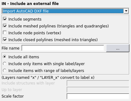
Figure 1. The IN - Include an external file (AutoCAD DXF) dialog.
Parameters:
- Include segments
- Check this item to include all wire segments that match the label selection.
- Include meshed polylines (triangles and quadrangles)
- Check this item to include meshed polylines (triangles and quadrangles) from the DXF file into the model.
- Include node points (vertex)
- Check this item to include node points from the DXF file into the model.
- Include closed polylines (meshed into triangles)
- Check this item to include closed polylines from the DXF file into the model. These structures will be meshed by PREFEKO.
Layers named n or LAYER_n (where n is an integer number) in the
.dxf model are converted to label n in Feko. For all structures for which no label is defined in
this format, the label specified with the last LA card preceding the IN card is
used. (If no such LA card is in effect, the default is label 0.) This label is used
in the label selection.
As for the other meshed CAD formats, dielectric triangles or metallic triangles which form the surface of a dielectric, are created by preceding the IN card with the appropriate ME card.
PREFEKO only processes the geometry information in the
section of the file between the keyword ENTITIES and
ENDSEC.
POLYLINE
structure (the layer of the VERTEX block for polylines is not
used).Segments are imported from blocks defined by the keyword LINE.
  0
LINE
  8
LAYER_01
  .
  .
 10
-0.0538
 20
0.0
 30
8.134
 11
5.110
 21
2.857
 31
0.0
  0
 ... (next keyword)
The group code 8 at a point below LINE indicates that the next line
contains the layer name. In this case, the layer will be converted to label 1. The
line will be imported and segmented if this label lies in the required range. (If
not, PREFEKO will search for the next occurrence of
LINE.) Next the x, y and z components of the start point follow
the group codes 10, 20 and 30; and those of the end point follow the codes 11, 21
and 31.
Here the start and end points are (x, y, z) = (-0.0538, 0.0, 8.134) and (5.110, 2.857, 0.0) respectively. If any of the coordinate group codes are absent (such as in a 2D model), the related coordinate is set to zero. The block is terminated by the group code 0. The wire is segmented according to the maximum segment length specified by the IP card, and the segments also have the radius specified by this card.
Meshed surfaces are imported from blocks denoted with the keyword
POLYLINE. This block contains the layer name (following the
group code 8 as before; if there is no group code 8 before the first
VERTEX, the label specified with the last LA card will be used)
and a number of VERTEX structures. There can be an arbitrary number
of VERTEX structures, but there should be at least four.
The POLYLINE structure is terminated by the keyword
SEQEND.
  0
POLYLINE
  8
LAYER_02
  .
  .
VERTEX
  .
  .
VERTEX
  .
  .
VERTEX
  .
  .
  0
SEQEND
There are two types of vertices. The first type defines points in space
  0
VERTEX
  8
LAYER_02
  .
  .
 10
7.919192
 20
3.393939
 30
0.0
  .
  .
  0
 ... (next keyword)
where the x, y and z components of the point follow the group codes 10, 20 and 30. The layer information is ignored. The second type of vertex is a “linker”.
 0
VERTEX
  8
LAYER_02
  .
  .
 70
   128
 71
     4
 72
     2
 73
     1
 74
     3
  .
  .
  0
... (next keyword)The four integer numbers after the group codes 71, 72, 73 and 74 give the indices of corners of the triangle or quadrangle. (In the case of a triangle one of these is absent.) PREFEKO divides each quadrangle into two triangles along the shortest diagonal.
In addition to being able to import meshed polylines, closed polylines can also be imported. These will be meshed into triangular patches during the import according to the meshing parameters set at the IP card.