Tutorial: Gravity Tilt Pouring Casting
Step through setup and defining the rotation for a gravity tilt pouring casting simulation.
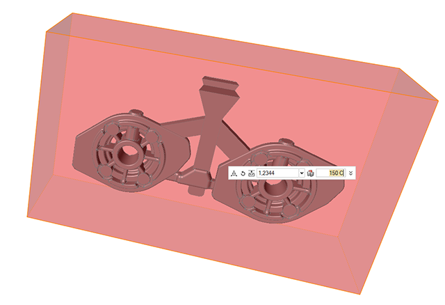
Model file is available in the tutorial_models folder in the installation directory in Program Files\Altair\2021\InspireCast2021\tutorial_models\Tilt-Pour.x_b.
Import Geometry
-
Click Open Model on the Files icon and browse to the
tutorial model file in the installation directory, or drag-and-drop the file
into the modeling window.

Designate a Casting Part
Select casting geometries with the Cast Part tool.
Important: A cast part must be defined before performing any other
operation.
-
On the Cast Part icon, click Designate
Casting Part.

-
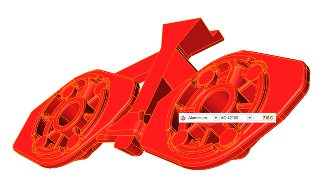
Left-click to select which candidate is a cast part.
Parts are automatically detected and highlighted based on your cursor position.The selected part is highlighted red.
-
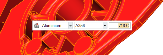
In the microdialog, select
Aluminum as the material and the first alloy,
A356, for the part.
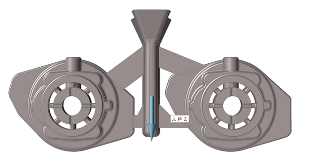
Set Gravity Direction
-
On the Cast Part tool, click Set Gravity
Direction.

-
Confirm that the part is correctly aligned with gravity.
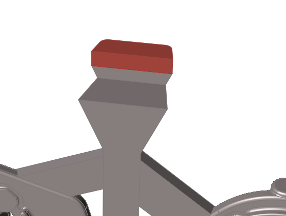
Set the Ingate
-
On the the Gate icon, click Designate
Surfaces as Gates.

-
Select surface to generate one.
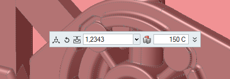
Add a Mold
-
Click the Components tool.

Click the Add/Edit Mold tool in the secondary tool group.
-
Select 12343 and enter 150 C.
Define Process Parameters
-
Click
 to select the
Gravity icon.
to select the
Gravity icon.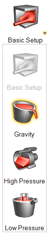
-
Select Tilt Pouring and select Y
as Rotation Axis.
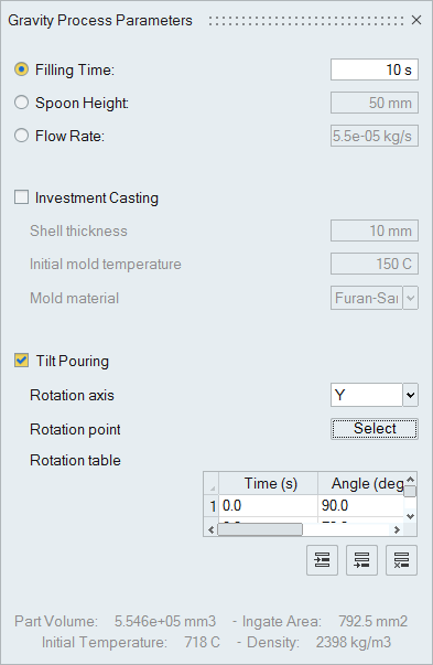
-
Click Select to choose Rotation
point then click the point on the geometry to define it.
Run Analysis
-
On the Analysis icon, click Run
Analysis.

-
Select Run filling analysis and Run
solidification analysis.
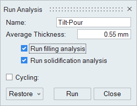
-
Click Run.
Note: Once the simulation calculation is finished, the green flag will appear on the analyze icon.

Note: The user can also select the results by clicking View Now under Run History.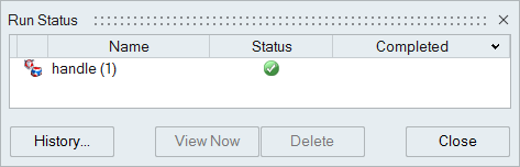
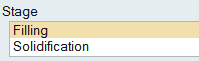
Analyze Results
-
Click Filling under Stage.
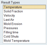
-
Click Temperature under Result
Types.
-
Click Play
to start the animation.
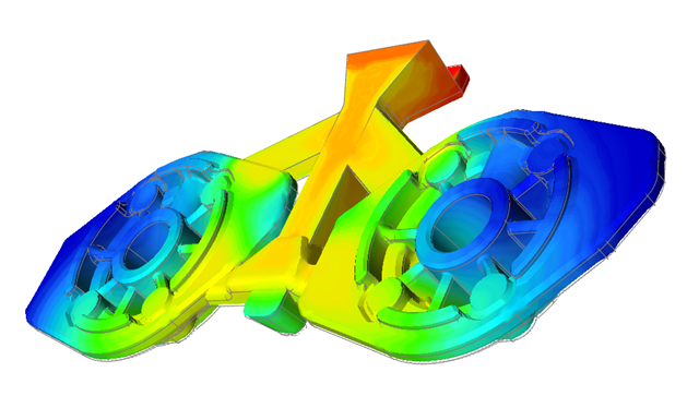
The part is filling smoothly and uniformly with no issues with temperature.
-
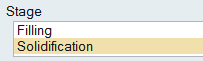
Click Solidification under Stage.
-
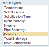
Click Porosity under Result
Types.
-
Click Play
to start the animation.
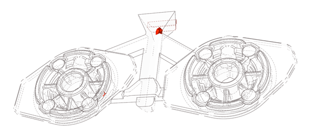
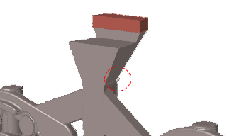
We can see that the location of the defect is in the filling system and not in the part itself.