Tutorial: Sleeve Component
Compare the solidification in a riser with that of risers with isothermal and exothermal sleeves.
In this exercise, you will learn how to analyze the effect a sleeve has on casting.
Model file is available in the tutorial_models folder in the installation directory in Program Files\Altair\2021\InspireCast2021\tutorial_models\sleeve.x_b.
Import Geometry
-
Click Open Model on the Files icon and browse to the
tutorial model file in the installation directory, or drag-and-drop the file
into the modeling window.

Designate a Casting Part
Select casting geometries with the Cast Part tool.
Important: A cast part must be defined before performing any other
operation.
-
On the Cast Part icon, click Designate
Casting Part.

-
Left-click to select which candidate is a cast part.
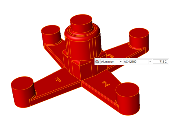
Parts are automatically detected and highlighted based on your cursor position. Since there is a single geometry the entire cast part will be automatically highlighted.The selected part is highlighted red.
-
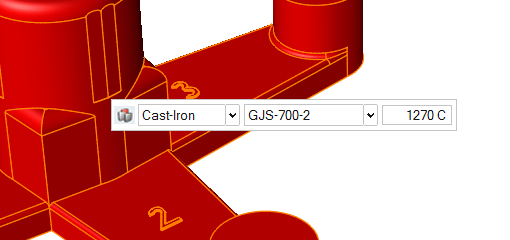
In the microdialog, select
Cast-Iron as the material and the first alloy,
GJS-700-2, for the part.
Add Risers
-
Click the Components tool.

Click the Add/Edit Riser tool in the secondary tool group.
-
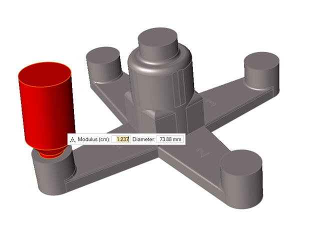
Click the center of the end of the first arm to create a riser and leave the
default values.
-
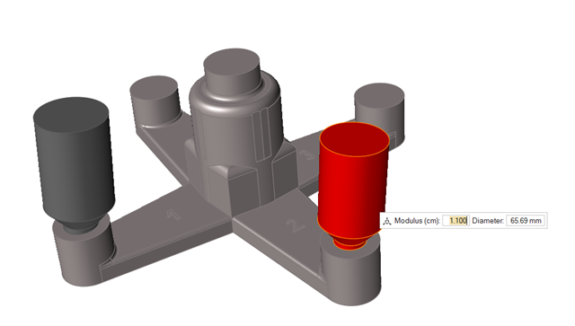
Click the center of the end of the second arm to create another riser and
change the Modulus to 1.1.
Note: For the second branch we are going to use an Isothermal Sleeve. We can decrease the riser size since an isothermal sleeve keeps heat and helps the riser feed the part longer.
-
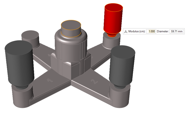
Click the center of the end of the third arm to create another riser and change
the Modulus to 1.0.
Note: For the third branch we are going to use an Exothermal Sleeve. We can decrease the riser size even more since an exothermal sleeve releases heat during its burn and helps the riser feed the part longer.
Add Sleeves
-
Click the Components tool.
Click the Add/Edit Sleeve tool in the secondary tool group.
-
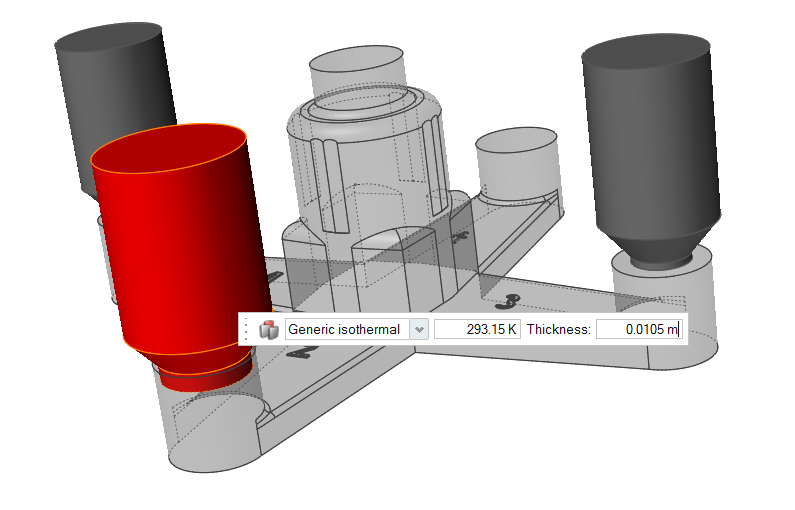
Click the riser on the second arm to create a Genetic
isothermal sleeve on top of it, and enter a temperature of
293.15K and Thickness of 0.0105m.
-
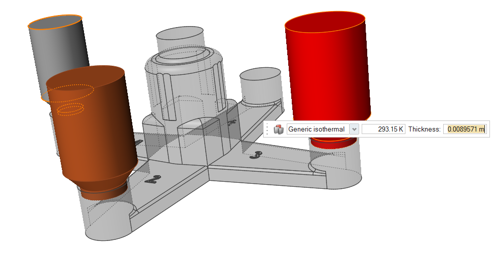
Click the riser on the third arm to create another Genetic
isothermal sleeve, and enter a temperature of 293.15K and
Thickness of 0.0089571m.
Run Analysis
-
On the Analysis icon, click Run
Analysis.

-
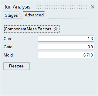
In the Run Analysis dialog, select the
Advanced tab to manually select mesh factors for
components like gate, mold, runner, riser, etc.
-
Click Run.
Note: The mold will automatically generate when you click Run.Note: Once the simulation calculation is finished, the green flag will appear on the analyze icon.

Note: The user can also select the results by clicking View Now under Run History.
Analyze Results
-
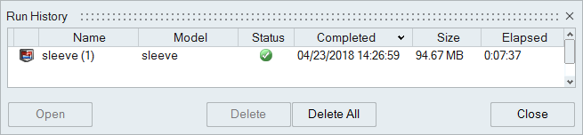
Click the Run History satellite
 on the
Analyze
on the
Analyze  tool.
tool.
-
Select the run and click Open.
-
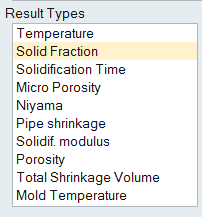
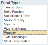
Click Solid Fraction under Result
Types.
-
Set the Solid Fraction percentage to
0.70.
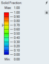
Note: The solid fraction value is set to 0.7 by default. In most cases, this corresponds to the value at which the liquid stops flowing. -
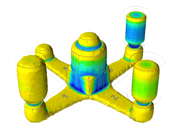
Click Play
to start the animation.
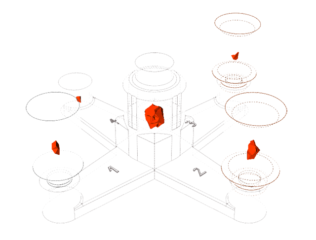
In the animation, solidified material (above 0.7) is transparent, while liquid material (below 0.7) is shown colored. Shrinkage porosity is more likely to occur in isolated areas.Despite the diminished size of the second and third risers, they are able to feed the part longer because of the effect of the sleeves.
-
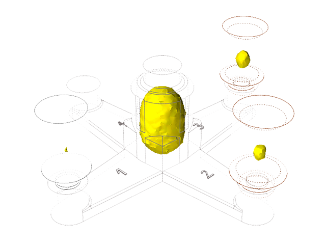
Click Porosity under Result
Types.
-
Set the percentage to 100%.
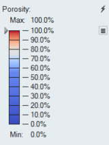
Despite the difference in sizes of the risers, all of the porosity is formed in them rather than in the part, thanks to the sleeves.