Tutorial: Core Component
See the difference in porosity of a solid model and the same model with a core.
In this exercise, you will learn how to analyze the effect a sand core has on casting.
Model file is available in the tutorial_models folder in the installation directory in Program Files\Altair\2021\InspireCast2021\tutorial_models\core.x_b.
Import Geometry
-
Click Open Model on the Files icon and browse to the
tutorial model file in the installation directory, or drag-and-drop the file
into the modeling window.

Designate a Casting Part
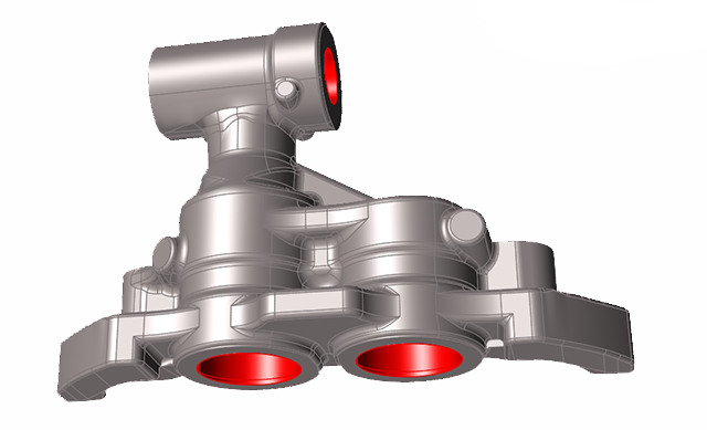
Select casting geometries with the Cast Part tool.
Important: A cast part must be defined before performing any other
operation.
-
On the Cast Part icon, click Designate
Casting Part.

-
Left-click to select which candidate is a cast part.
Parts are automatically detected and highlighted based on your cursor position. Since there is a single geometry the entire cast part will be automatically highlighted.The selected part is highlighted red.

-
In the microdialog, select Steel
as the material and the first alloy, AISIF91, for the
part.

Set Gravity Direction
-
On the Cast Part tool, click Set Gravity
Direction.

-
Click the Gravity icon in the microdialog to align the geometry vertically to the normal of
a selected surface.

Note: The gravity direction will always be in the Z-axis. -
Click one of the bottom surfaces of the part.
 The part will automatically be positioned with the gravity perpendicular to the selected surface.
Add a Gate
-
On the Gate icon, click Add/Edit
Gate.

-
Select a surface of the model to place the gate there, and enter the dimensions
in the microdialog.

Add a Core
-
Click the Components tool.

Click the Core tool in the secondary tool group.
-
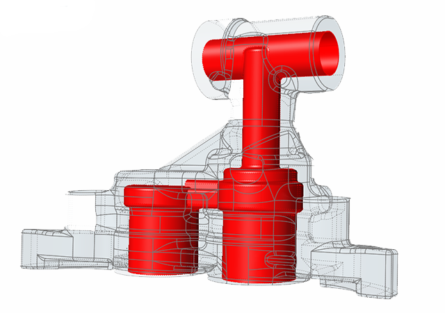
Left-click to select which candidate is a core and automatically create the
core volume.
Parts are automatically detected and highlighted based on your cursor position.The selected part is highlighted red.
-
In the microdialog, select
Silica-Sand as the material.


Run Analysis
-
On the Analysis icon, click Run
Analysis.

-
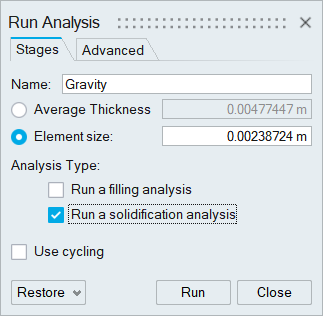
In the Run Analysis dialog, select the
Stages tab and enter the Element
size manually or define the Average
Thickness . You can also select number of cycles in the process
by selecting Use cycling.
-
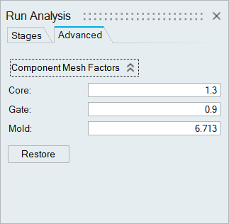
In the Run Analysis dialog, select the
Advanced tab to manually select mesh factors for
components like gate, mold, runner, riser, etc.
-
Click Run.
Note: The mold will automatically generate when you click Run.Note: Once the simulation calculation is finished, the green flag will appear on the analyze icon.

Note: The user can also select the results by clicking View Now under Run History.
Analyze Results
-
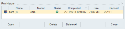
Click the Run History satellite
 on the
Analyze
on the
Analyze  tool.
tool.
-
Select the run and click Open.
-
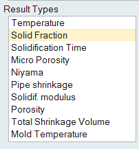
Click Solid Fraction under Result
Types.
-
Set the Solid Fraction percentage to
0.70.
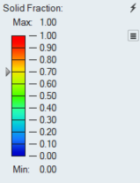
Note: The solid fraction value is set to 0.7 by default. In most cases, this corresponds to the value at which the liquid stops flowing. -
Click Play
to start the animation.
In the animation, solidified material (above 0.7) is transparent, while liquid material (below 0.7) is shown colored. Shrinkage porosity is more likely to occur in isolated areas.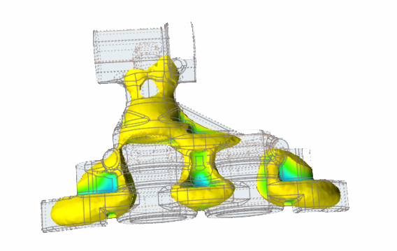
-
Click Porosity under Result
Types.
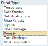
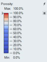
-
Set the percentage to 100%.
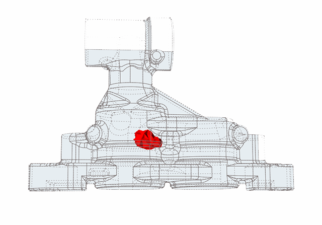
Shrinkage Porosity is distributed in 3 different regions at the bottom of the part.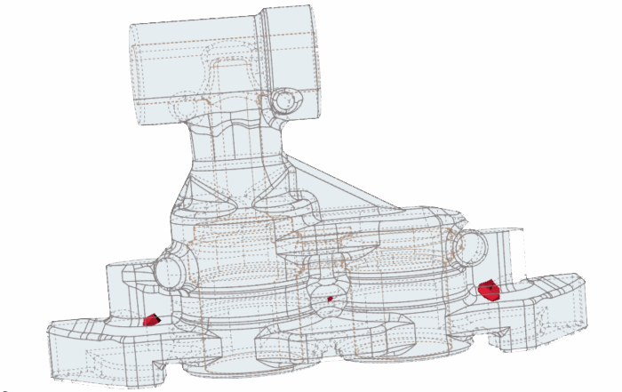
Make Solid
-
In the Modeling Window, select the core and right-click
to delete it.
-
Click the Simplify tool.

Click the Holes tool in the secondary tool group.
-
Left-click on the interior shape to select and close the internal hole.
Candidates are automatically detected and shown in red based on your cursor position.The total number of holes is displayed above the Holes tool.
We now have a totally solid geometry to compare with the simulation with the core.
Run Analysis
-
On the Analysis icon, click Run
Analysis.
-
In the Run Analysis dialog, select Run
solidification analysis and enter an Average Thickness of 4
mm.

-
Click Run.
Note: Once the simulation calculation is finished, the green flag will appear on the analyze icon.
Note: The user can also select the results by clicking View Now under Run History.
Analyze Results
-
Click Solid Fraction under Result
Types.
-
Set the Solid Fraction percentage to
0.70.
Note: The solid fraction value is set to 0.7 by default. In most cases, this corresponds to the value at which the liquid stops flowing. -
Click Play
to start the animation.
In the animation, solidified material (above 0.7) is transparent, while liquid material (below 0.7) is shown colored. Shrinkage porosity is more likely to occur in isolated areas.Note: When you compare this model result with the previous run that had a core, you will notice a difference in the solidification behavior. This simulation shows that all of the contraction during solidifcation is being concentrated in a single region.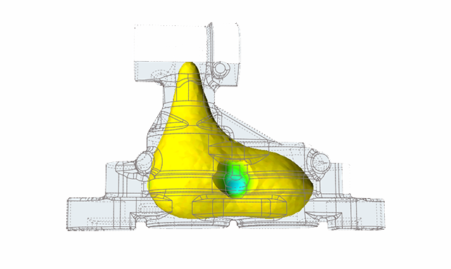
-
Click Porosity under Result
Types.
-
Set the percentage to 100%.
Note: Comparing this model with the previous one, we can see the porosity differences in the simulations. The porosity is now concentrated in a single region and has dramatically increased in size.