Indoor MIMO Through Post-Processing
Perform indoor network planning with MIMO using post-processing.
Model Type
In this indoor network planning project, the geometry of a multi-story building is preprocessed to use intelligent ray tracing model (IRT).
Sites and Antennas
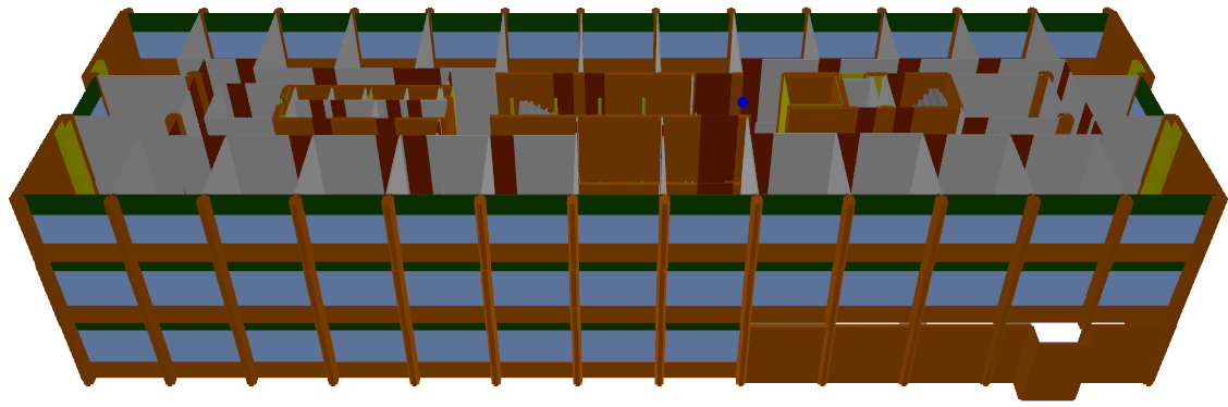
Figure 1. The multi-story building in 3D.
Air Interface
The air interface is based on long term evolution (LTE). Orthogonal frequency division multiple access (OFDM/SOFDMA) is selected for multiple access. No MIMO technology is assigned (yet) for the carrier. MIMO related results are derived through post-processing once the propagation results for the isotropic antenna are known.
Computational Method
The deterministic mode uses Fresnel equations for the determination of the reflection and transmission loss and geometrical theory of diffraction for the determination of the diffraction loss. This approach uses four physical material parameters, namely thickness, permittivity, permeability, and conductivity.
Results
Propagation results show at every location the power received from the transmitting antenna. Results are calculated for a single prediction plane at a height of 8.5 m.
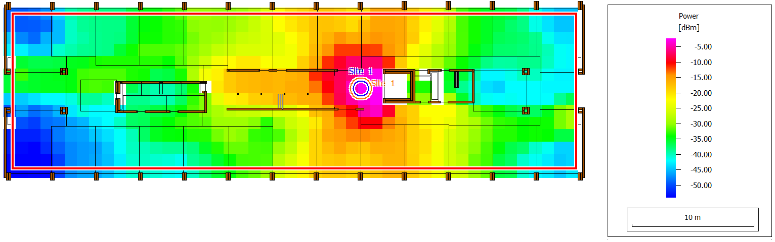
Figure 2. Received power on the prediction plane.
On the Postprocessing of Mobile station dialog, click Edit Parameters to define antenna patterns and (optionally) small arrays. This can be done for both the base station and the mobile station. Thereafter, click the Start Computation button.
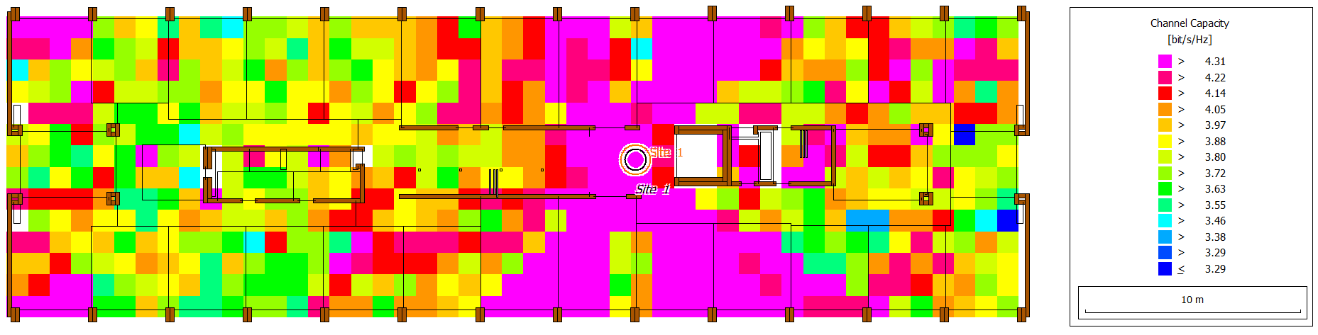
Figure 3. Channel capacity (MS) results for a MIMO array.
These results are obtained with imported antenna patterns (not part of this example). The effects of the antenna pattern, array orientation and antenna spacing can readily be investigated without solving the entire propagation project again.