Indoor LTE with Leaky Feeder Cable
Perform indoor network planning with LTE and leaky feeder cables.
Model Type
The model consists of a large single-story building with leaky feeder cables installed along a horizontal path. The cable has apertures along its entire length to allow transmission and reception by means of signal leakage. Amplifiers are used to boost the signal along these cables to improve signal transmission from the transmitter to the receiver.
Sites and Antennas
Air Interface
The air interface is defined by an LTE wireless standard LTE_LeakyFeeder.wst file. (Orthogonal Frequency division multiple access (OFDM/SOFDMA) was selected for multiple access. Two-streams MIMO technology is used.
Computational Method
Results
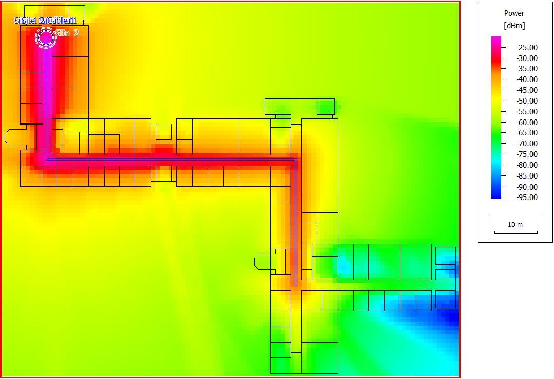
Figure 1. The power for Site 1.
Figure 2. The power for Site 2.
- minimum required transmitter power
- maximum achievable received signal strength
- reception probability
- data rate
- maximum number of parallel streams
- maximum signal-to-noise-and-interference ratio (SNIR) for all modulation and coding schemes, and for both uplink and downlink
An example of signal-to-noise-and-interference ratio (SNIR) in the downlink is displayed in Figure 3. Near the lower-right corner, both the signal level and the SNIR are low. Consequently, communication in that area is limited to modes with lower data rates.
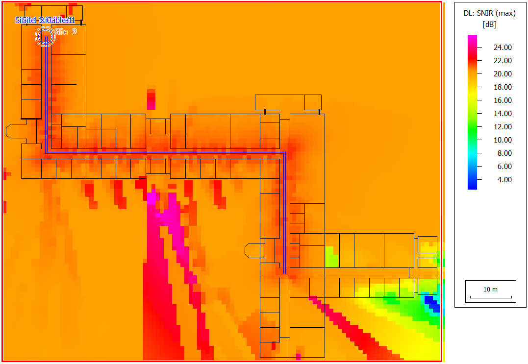
Figure 3. The maximum downlink SNIR.