Digital Video Broadcasting, Rural/Suburban
Calculate the power coverage of four digital video broadcasting transmitters in a rural/suburban scenario.
Digital Video Broadcasting Standards
Digital Video Broadcasting (DVB) is a set of international standards for digital television. The different standards explained in this model are DVB-H, DVB-T, and DVB-T2.
DVB-H (Digital Video Broadcast - Handheld) is a technical term used for bringing broadcast services to mobile handsets. DVB-T (Digital Video Broadcast - Terrestrial) is a European based standard for the broadcast transmission of digital terrestrial television. DVB-T2 (Digital Video Broadcasting - Second Generation Terrestrial) is the extension of the DVB-T television standard. This system transmits compressed digital audio, video, and other data using OFDM modulation to offer a higher bit rate, which is suitable for terrestrial HD TV signal broadcasts.
Model Type
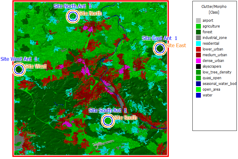
Figure 1. Clutter/morpho data
Site and Antennas
Air Interface
All parameters related to the selected air interface are specified on the Air Interface tab. Settings for orthogonal frequency division multiple access can also be accessed here.
Computational Method
Results
Propagation results in this project include power coverage for each transmitting antenna of all four sites. This is the power that an isotropic receiver at a given position would receive from the transmitter.
- Strongest transmitter
- Best server
- Signal power
- Signal-to-Noise-and-Interference Ratio (SNIR)
Figure 2. The strongest transmitter for every location.