Wind Tunnel Setup
Examples in this section are created using Altair Virtual Wind Tunnel. Refer to the Altair Virtual Wind Tunnel User Guide for detailed information on how to use Virtual Wind Tunnel.
Tunnel Definition and Floor Boundary Conditions
- Standard open-road simulation
- Wind tunnel correlation
In the case of wind tunnel correlation, moving belts can be modeled on the floor. This creates a moving wall boundary condition on the set belt locations. A boundary layer suction location can be set upstream of the test setup. All floor elements except the belts are set to stationary wall past this suction location. When using belts, one should always set a boundary layer suction location. A certain resolution is needed to enable correct modeling of the boundary layer past the suction location; this will be covered later in this chapter.
Domain Size and Blockage Ratio
- Suggested upstream dimensions about 5 car lengths, 10 downstream car lengths
- Suggested about 4 car lengths or 12 car widths for the plus and minus y dimensions,
- Suggested about 6 car lengths or 20 car heights in z, keeping in mind to adjust for reaching a blockage ratio of the order of around 0.5%
| Recommended domain size in car lengths | |
|---|---|
| +x | 5 |
| -x | 10 |
| +y | 4 (or 12 widths) |
| -y | 4 (or 12 widths) |
| +z | 6 (or 20 heights) |
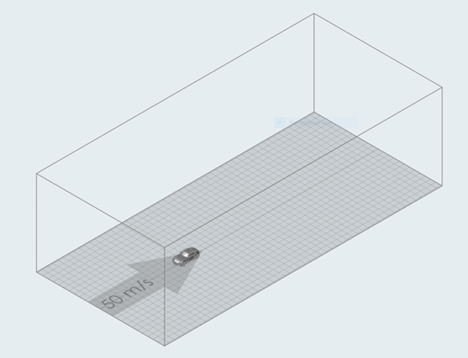
Figure 1. Simulation domain, as shown in VWT
Inflow Mach Number
In LBM, the Mach number can be set up independently from the inlet velocity. A higher Mach number will speed up the simulation for the same physical time as acoustic wave speeds are getting closer to the convective speed of the aerodynamics investigation. LBM has its limits in terms of Mach numbers achievable. Increasing the Mach number gives rise to compressibility effects as well. Therefore, it is recommended practice that no local section of the flow is above a local Mach number of Mmax=0.4. For a passenger vehicle, it is assumed that the ratio between maximum relevant velocity and inlet velocity Umax/Uinflow is around 1.5. A maximum inflow Mach number of Minflow=0.25 is, therefore, recommended, which gives assumed maximum Mach number locally of Mmax=1.5*0.25=0.375.
The maximum velocity and velocity ratio Umax/Uinflow can be set in VWT. Alternatively, in the .xml file, you can directly adjust the Mach scaling factor. A Mach scaling factor of 1 yields the physical Mach number of the simulation, matched based on the fluid properties and inflow conditions.
For example, an inflow velocity of Uinflow=40 m/s, and a speed of sound based on fluid properties of 340 m/s gives a Mach number of M=40/340=0.118. In order to set the inflow to a Mach number of 0.25 as per recommendation, a Mach scaling factor of 0.25/0.118=2.13 is needed.
Run Time and Averaging Time
As ultraFluidX provides a full Large Eddy Simulation (LES), the flow is inherently fluctuating and changing over time. A certain number of flow-passes are required to initialize the flow field and converge on the flow fluctuations around a steady mean. It is recommended to wait for 15 flow passes to initialize and then measure the relevant quantities for another 15 flow passes.
- Total simulation time 4s
- Start of averaging time 2s (measuring between 2s and 4s)