Generate Custom Refinement Zones
Create an arbitrary refinement zone around a closed volume.
Create custom refinement zones in the following ways:
-
Use the Custom tool.
-
From the ultraFluidX
ribbon, Setup group,
click the Mesh Controls
tool.
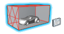
Figure 1. -
From the secondary tool set, click the body of the
Custom tool.
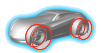
Figure 2. -
Enter a value for Level in the microdialog.
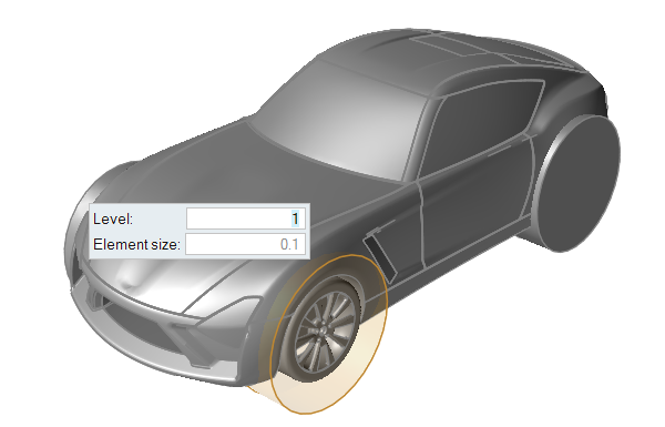
Figure 3.Note: All mesh controls in the model are defined relative to the far field size, and must be a power of 2 of the far field size. For example, if you define a far field mesh size of 1 m, the available refinement sizes will be 0.5, 0.25, 0.125, etc
-
From the ultraFluidX
ribbon, Setup group,
click the Mesh Controls
tool.
- Right-click on a part in the modeling window or the Model Browser and select from the context menu.
- Select a part in the modeling window or the Model Browser then change the Identify As field to Custom Zone in the Property Editor.
Tip: Modify the refinement zone's dimensions in the Property Editor.