Before creating a belt
system, first create the wind tunnel and identify wheels.
From the ultraFluidX ribbon,
Setup group, click
the Belt System tool.
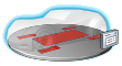
Figure 1.
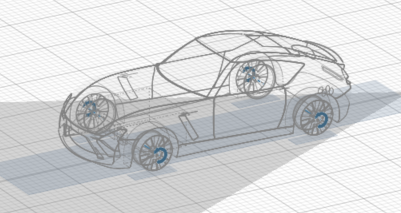
By default, five patches are created on the wind tunnel ground for
modeling the belt system.Figure 2.
Define the belt system's location and sizes in the following ways:
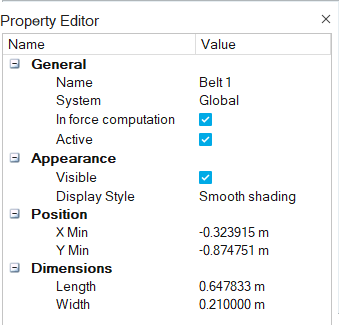
Edit belts individually by selecting a belt in the Model Browser or modeling window
and modifying its properties in the Property Editor.Figure 3.
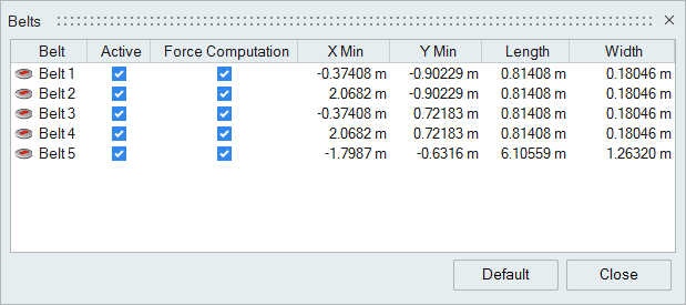
Edit the belt system by clicking Belt System
tool satellite icon .Figure 4.
If a belt system is defined and the Moving Ground check box is active in the
Write to ultraFluidX dialog, the belt patches are modeled as a
moving wall (moving with the inflow velocity) and the rest of the wind tunnel ground is
modeled as a stationary wall. If a belt system is defined and the Moving Ground check
box is inactive, the complete wind tunnel ground is modeled as a stationary wall. If no
belt system is defined and the Moving Ground check box is active, the complete wind
tunnel ground is modeled as a moving wall.
Note: The solver will always respect the
settings for boundary layer suction. Any portion of the ground that is upstream of
the boundary layer suction location will be treated as a slip wall.
 .
.