Surface Results
The Surface Results tool enables the user to derive additional results only definable on surfaces.
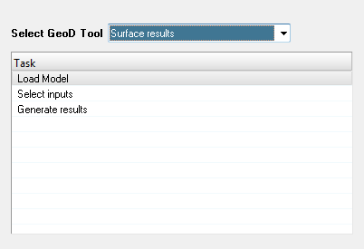 Figure 1.
 Note:
- Only the results file with the 2D surface mesh and the matching results are supported as inputs to calculate planar results (surface) tool.
- The loading of the model and result files can be done either before or after the launching of the tool.
-
Select the tool from the Select GeoD Tool drop down list.
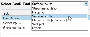 Figure 2.
 -
Click Select inputs task.
The Select inputs panel is displayed.
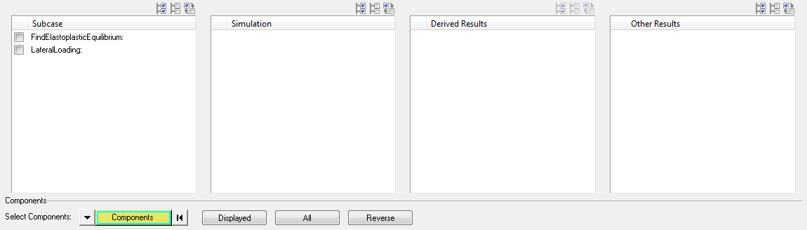 Figure 3.
 -
Click the Select All
 button.
All available sub cases are selected.
button.
All available sub cases are selected. -
Click the Select None
 button.
All available sub cases are deselected.
button.
All available sub cases are deselected. -
Click the Select Reverse
 button.
Subcase selection is reversed.
button.
Subcase selection is reversed. -
Select the required simulation(s) from the Simulation table.
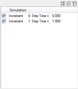 Figure 4.
 -
Select the required stress result types from the Derive Results Based On table.
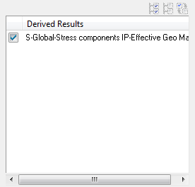 Figure 5. Note: By default, the global stress with IP-Effective (Integration Point) is selected. The user can select only one stress type for deriving the planar results.
 -
Select the required results from the Results to Propagate table to propagate (copy) into the new h3d
file.
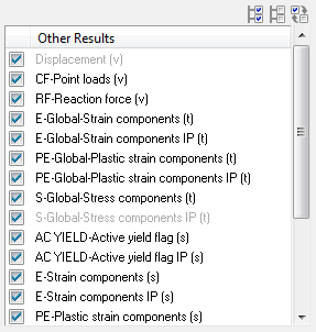 Figure 6. Note: The user can propagate the results from source file to target h3d file by selecting the results from the Results to Propagate table. Uncheck the results that are not required to be propagated into the new h3d file.
 -
Click the Components button.
Extended Entity Selection window is displayed.
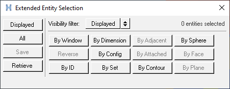 Figure 7.
 -
Click the Displayed button adjacent to the Components button.
 Figure 8. The components are highlighted in the graphics area.
 -
Click Clear
Collector
 to reset or clear the component selection.
-
Select the required results from the Standard Results table.
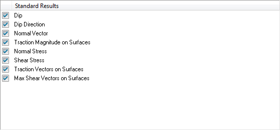 Figure 9.
 -
Select Material File.
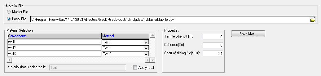 Figure 10.
 - Master File - Select this option to source materials from hvMasterMatFile.csv.
- Local File - Select this option to source materials from the user defined file.
Note: The user is required to select the corresponding
For Local File Selection
-
Click Save Mat button.
A confirmation message is displayed.
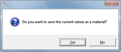 Figure 11.
 -
Click Yes and enter the Material
Name.
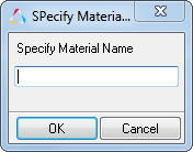 Figure 12.
 -
Click the file browser button
 in the Output file text field, after defining the required
inputs.
A file selection window is displayed.
in the Output file text field, after defining the required
inputs.
A file selection window is displayed. -
Click Generate H3D.
An information message is displayed.
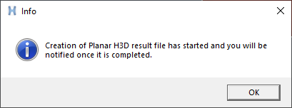 Figure 13.
 -
Once the H3D file is generated, a confirmation window is displayed.
 Figure 14.
 -
Load the h3d file with surface results into HyperView window, after the
completion of the process.
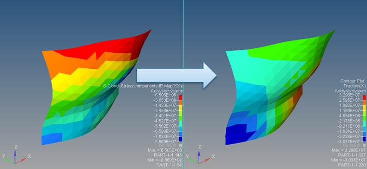 Figure 15.