HM-4615: Model Import, Airbags, Export Displayed, and Contacts with LS-DYNA
In this tutorial you will define the following: *AIRBAG_WANG_NEFSKE for the airbag mesh geometry; initial velocity of 3 mm/ms in the negative x-direction for the head with *INITIAL_VELOCITY_GENERATION; a contact between the airbag and head with *ICONTACT_AUTOMATIC_SURFACE_TO_SURFACE; *CONTACT_AIRBAG_SINGLE_SURFACE for the airbag; and a contact between the plate and the airbag with *CONTACT_NODES_TO_SURFACE.
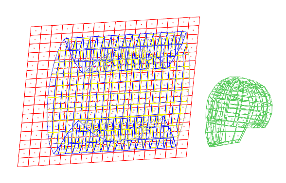
Figure 1.
LS-DYNA Overview
In this section, you will learn how to import a LS-DYNA model, export displayed, and create and review contacts.
Import a LS-DYNA Model
- Warning and Error Messages
- When importing a LS-DYNA model, Engineering Solutions warning and error messages will be written to a file named dynkey.msg or dynaseq.msg, depending on the FE input translator being used. This file is created in the same folder from which Engineering Solutions was started.
- Unsupported Cards
- On import, the LS-DYNA cards not supported by Engineering Solutions are written to the unsupp_cards panel. Access this panel by clicking from the menu bar. Unsupported cards will be exported with the remaining model.
- LSTC Dummy Files
- You can read LSTC Hybrid III dummy files into Engineering Solutions by first converting the tree file to FTSS/ARUP tree file format.
- Include Files
- Engineering Solutions supports *INCLUDE. When Include files are imported into Engineering Solutions, the IDs of non-existing entities are maintained and will not be used for new entities. Use the Include files import option to specify whether to merge, preserve, or skip Include files on import. Access this option by clicking from the menu bar.
Export Displayed
From the Export - Solver Deck tab, select the Export Displayed option to export only displayed nodes and elements. Only model data associated to the displayed nodes and elements are exported. This model data includes materials and their associated curves, properties, portions of contacts, and output requests.
Create and Review Contacts
Table 1 describes how all secondary and main set types are created and specified in contacts.
| Secondary and Main Set Type | LS-DYNA card | Panel Used to Create Card | Equivalent type in Interfaces panel, add subpanel | ||
|---|---|---|---|---|---|
| EQ. 0: set segment id | *SET_SEGMENT | set_segment (contactsurfs) or … | csurfs | ||
| Interfaces, add subpanel | entity | ||||
| EQ. 1: shell element | *SET_SHELL_Optio | Entity Sets or… | sets | ||
| set id | n | Interfaces, add subpanel | subpanel entity | ||
| EQ. 2: part set id | EQ. 2: part set id | Entity Sets or… | Interfaces, add subpanel | split | comps |
| EQ. 3: part id | *PART | Collectors | comps | ||
| * EQ. 4: node set id | *SET_NODE_Option | Entity Sets or… | sets | ||
| Interfaces, add subpanel | entity | ||||
| * EQ. 5: include all | Interfaces, add subpanel | all | |||
| * EQ. 6: part set id for exempted parts | *SET_PART_LIST | Interfaces, add subpanel and then card image subpanel | sets | ||
- Add Subpanel
- While the Interfaces panel, add subpanel has several main and secondary entity types to choose from in order to specify the LS-DYNA main or secondary set for a *CONTACT, only the valid main and secondary types are selectable for the particular contact you are creating.
- Review Contacts
- Review contacts by clicking review in the Interfaces panel, add subpanel.
Load the LS-DYNA User Profile
In this step, you will load the LS-DYNA user profile in Engineering Solutions.
- Start Engineering Solutions Desktop.
- In the User Profile dialog, set the user profile to LsDyna.
Import the LS-DYNA Model
In this step, you will import the LS-DYNA model file into Engineering Solutions.
Define *AIRBAG_WANG_NEFSKE
In this step, you will define *AIRBAG_WANG_NEFSKE for the airbag mesh geometry.
-
Create a set of parts, *SET_PART_LIST, containing the AirbagFront and
AirbagRear components.
-
In the Model Browser, right-click and select from the context menu.
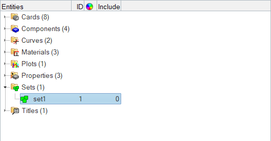
Figure 2.A new set opens in the Entity Editor. -
For Entity IDs, click .
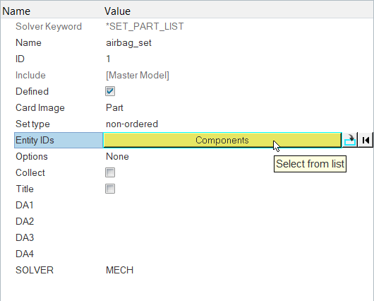
Figure 3. -
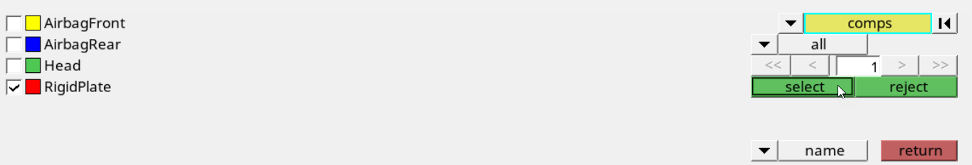
In the Select Components dialog, select
AirbagFront and
AirbagRear and then click OK.
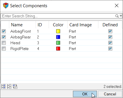
Figure 4.
-
In the Model Browser, right-click and select from the context menu.
-
Define the airbag (*AIRBAG_WANG_NEFSKE).
-
In the Solver Browser, right-click and select from the context menu.
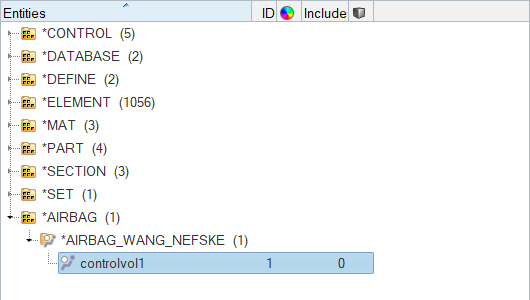
Figure 5.A new control volume opens in the Entity Editor. -
Set the entity selector to Sets as seen in Figure 6.
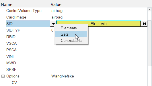
Figure 6. -
Click Set.
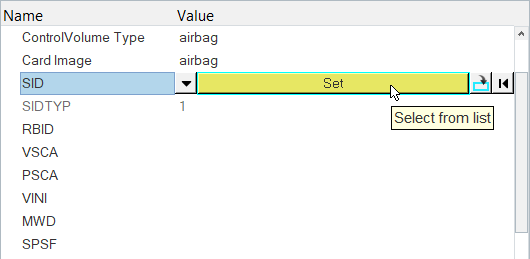
Figure 7. -
In the Select Set dialog, select
airbag_set and then click OK.
Note: The parts in this set define the airbag's geometry.
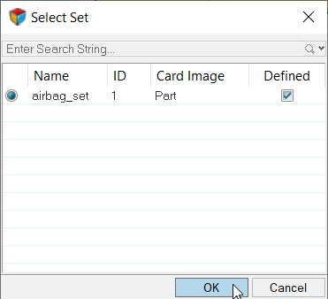
Figure 8.
-
In the Solver Browser, right-click and select from the context menu.
-
Define an initial velocity of 3 mm/ms in the negative xdirection for the head
with *INITIAL_VELOCITY_GENERATION.
-
In the Solver Browser, right-click and select from the context menu.
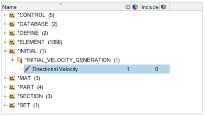
Figure 9.A new load opens in the Entity Editor. -
For Entity IDs, click .
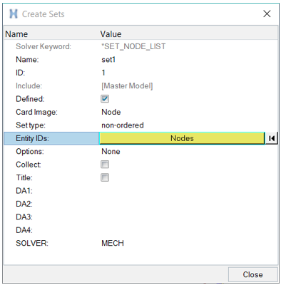
Figure 10. -
Select the Head checkbox as seen in Figure 11.
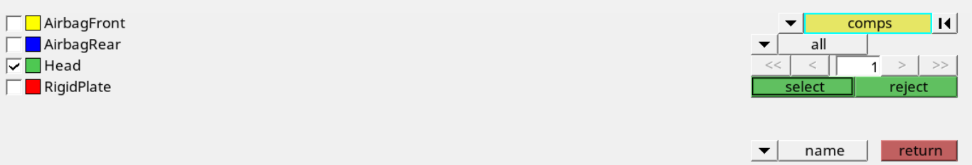
Figure 11. -
In the Solver Browser, *INITIAL folder,
*INITIAL_VELOCITY_GENERATION subfolder, right-click on
velocity and select
Review from the context menu.
Engineering Solutions highlights the load and greys out all of the other entities as seen in the following image.
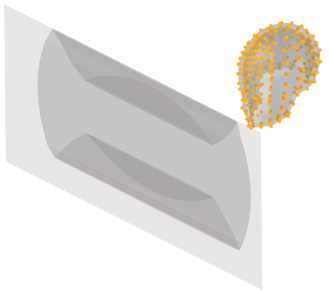
Figure 12.
-
In the Solver Browser, right-click and select from the context menu.
Define a Contact Between the Airbag and the Head
In this section, you will define a contact between the airbag and the head with *CONTACT_AUTOMATIC_SURFACE_TO_SURFACE.
-
Create a Engineering Solutions group with the card image SurfaceToSurface.
-
In the Solver Browser, right-click and select from the context menu.
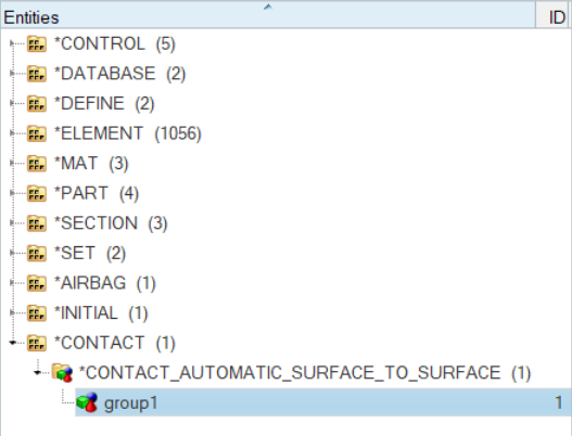
Figure 13.A new group opens in the Entity Editor.
-
In the Solver Browser, right-click and select from the context menu.
-
View the main and secondary entities.
Tip: In this step, the Airbag_Head group should be selected in the Solver Browser.
-
In the Solver Browser, right-click on
Airbag_Head and select
Review from the context menu.
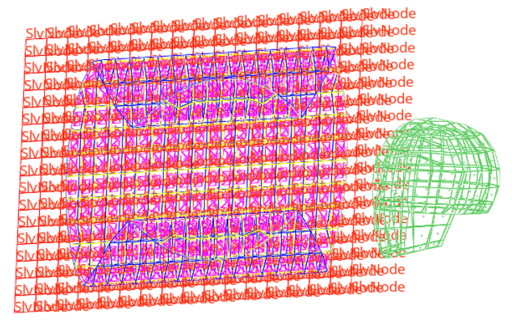
The main and secondary entities temporarily display in blue and red. The other entities temporarily display grey.
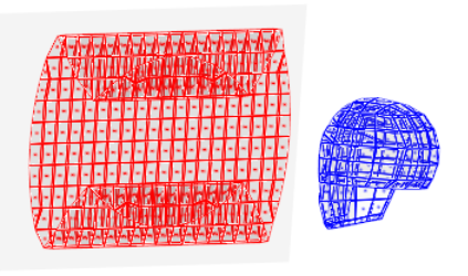
Figure 14.
-
In the Solver Browser, right-click on
Airbag_Head and select
Review from the context menu.
-
Define *CONTACT_AIRBAG_SINGLE_SURFACE for the airbag.
-
In the Solver Browser, right-click and select from the context menu.
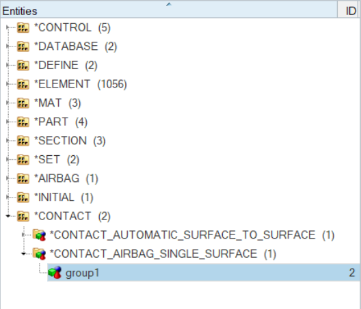
Figure 15.A new group opens in the Entity Editor.
-
In the Solver Browser, right-click and select from the context menu.
-
View the secondary entities.
Tip: In this step, the airbag group should be selected in the Solver Browser.
-
In the Solver Browser, right-click on
airbag and select
Review from the context menu.
The main and secondary entities temporarily display white and red. The other entities temporarily display grey.
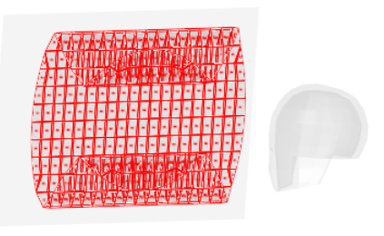
Figure 16.
-
In the Solver Browser, right-click on
airbag and select
Review from the context menu.
Define a Contact Between the Plate and the Airbag
In this step, you will define a contact between the plate and the airbag with *CONTACT_NODES_TO_SURFACE.
-
Define the AirbagRear component to be the main surface with a main type of 0,
set segment ID.
-
In the Solver Browser, right-click and select from the context menu.
Figure 17.A new contactsurf opens in the Entity Editor. -
In the panel area, set the second switch to
elems as seen in Figure 18.
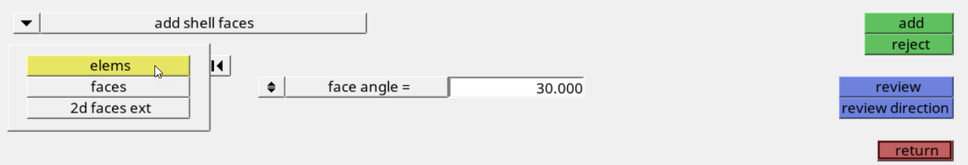
Figure 18. -
Click add.
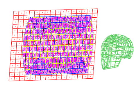
Figure 19.
-
In the Solver Browser, right-click and select from the context menu.
-
Reverse the contactsurf’s pyramids so they point out of the airbag.
-
In the panel area, set the first switch to
adjust contact direction as seen in Figure 20.
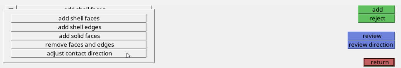
Figure 20. -
Click reverse.
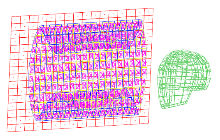
Figure 21.
-
In the panel area, set the first switch to
adjust contact direction as seen in Figure 20.
-
Create a *CONTACT_NODES_TO_SURFACE card.
-
In the Solver Browser, right-click and select from the context menu.
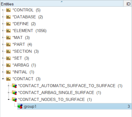
Figure 22.A new group opens in the Entity Editor.
-
In the Solver Browser, right-click and select from the context menu.
- Define the plate to be the contact’s secondary surface with a secondary type of 4, node set ID.
-
View the main and secondary entities.
-
In the Solver Browser, *CONTACT folder, *CONTACT
NODES TO SURFACE subfolder, right-click on
Airbag_Plate and select
Review from the context menu.
The main and secondary entities temporarily display blue and red. The other entities temporarily display grey.
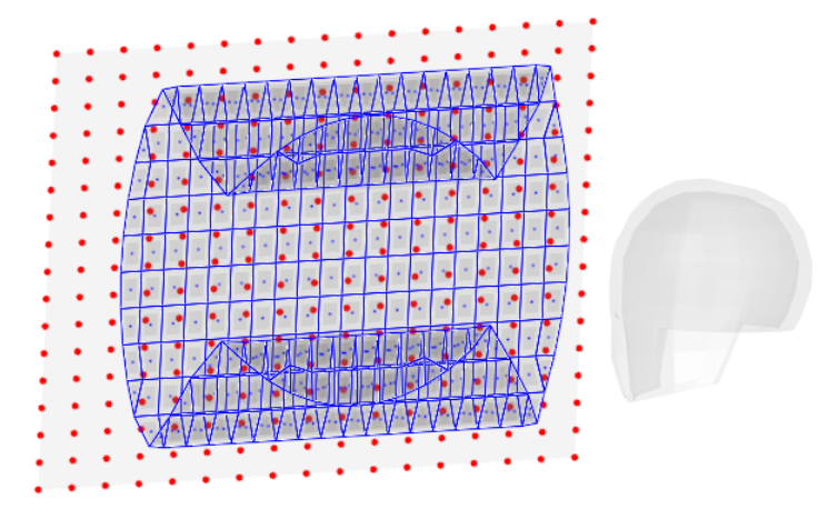
Figure 25.
-
In the Solver Browser, *CONTACT folder, *CONTACT
NODES TO SURFACE subfolder, right-click on
Airbag_Plate and select
Review from the context menu.
Review the Created Solver Entities
In this step, you will review the created solver entities using the Solver Browser.
-
In the Solver Browser, *CONTACT folder,
*CONTACT_AIRBAG_SINGLE_SURFACE subfolder, right-click on
airbag and select Review from
the context menu.
Note: Only secondary (red) entities are shown because there are no main entities for this type of contact.The main and secondary entities temporarily display blue and red. The other entities temporarily display grey.
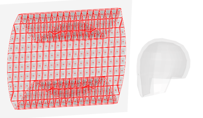
Figure 26. -
In the Solver Browser, *CONTACT folder, *CONTACT NODES TO
SURFACE subfolder, right-click on Airbag_Plate and select
Isolate Only from the context menu.
Tip: If main and secondary entities are not visible, make sure the Show/Isolate/IsolateOnly/Attached checkbox is selected in the Options tab of the Browser Configuration dialog. Access the Browser Configuration dialog by right-clicking in the Model Browser and selecting Configure Browser from the context menu.Only the elements/components that are implicated in this contact display as seen in the following image.
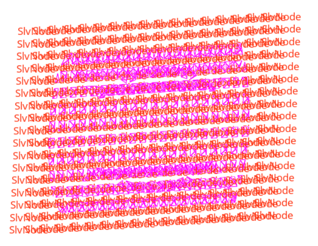
Figure 27. -
In the Solver Browser, *CONTACT folder,
*CONTACT_AIRBAG_SINGLE_SURFACE subfolder, right-click on
airbag and select Show from
the context menu.
The entire airbag displays as seen in the following image.
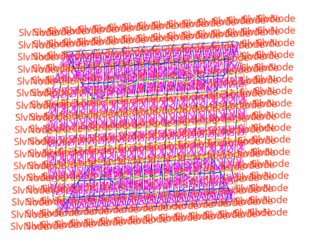
Figure 28.
Export the Model
In this step, you will export the model to an LS-DYNA 971 formatted input file.
-
Next to Export options, click
 .
.
Submit the Input File
In this step, you will submit the LS-DYNA input file to LS-DYNA 970.
- From the Start Menu, open the LS-DYNA Manager program.
- From the solvers menu, select Start LS-DYNA analysis.
- Load the airbag_complete.key file.
- Start the analysis by clicking OK.
View the Results
In this tutorial, you will view the results in HyperView.