CFD-1100: Create a Hybrid Grid with Varying Boundary Layer Thickness
In this tutorial, you will learn to generate boundary layer type meshes with an
arbitrary number of layers and thickness distribution, which can be used for CFD
applications, molding simulations, or other processes. You will also generate automatically
a distributed thickness distribution to prevent boundary layer interference /collision in
zones where the distance between opposing walls is too small to accommodate the baseline or
nominal boundary layer thickness.
The
model file used in this exercise can be found in the es.zip file.
Copy the file(s) from this directory to your working directory.
Load the CFD User Profile
From the menu bar, click Preferences > User Profiles or click the Load User Profile icon,
, on
the Standard toolbar.
Click Engineering Solutions > CFD.
Click OK.
Open the Model File
On the Standard toolbar, click the Open Model
icon.
Select the molding1.hm file.
Click Open to load this file containing the surface
mesh.
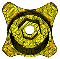
Inspect the surface elements that will be used to generate the volume
mesh.
The boundary mesh can have any combination of tria/quad
elements. You will generate boundary layers on all the surface elements
contained in the collector named wall.Figure 1.
Check That All the Elements in Collector Wall Define a Closed Volume
Click Mesh > Check > Components > Edges to open the Edges panel.
Click comps and select the collector
wall.
Click find edges.
A message indicating that no edges were found will appear on the
status bar.
Toggle free edges to
T-connections.
Select the collector wall again and click find
edges.
The status bar will display, “No T-connected
edges were found.”
Create the CFD Mesh
Click Mesh > Volume Mesh 3D > CFD Tetramesh to open the CFD Tetramesh panel.
Select the Boundary selection subpanel. You will need to
first select all the elements/components that define the surface area on which
you need to generate boundary layers. This is done by selecting the
elements/components under the With BL (float) selector.
Under the heading With BL (float), click comps and
select the collector wall.
Verify that the switch below the W/o BL (float) selector is set to
Remesh.
This means that the meshes in the zones defined by the collector wall will be
remeshed after being deformed by the boundary layer growth from adjacent surface
areas.
Select Smooth BL.
This option is strongly recommended for most cases because it produces
boundary layers with more uniform thickness and better element quality.
Click the BL parameters subpanel.
All the data that has been entered in the Boundary selection subpanel is
stored.
Select the options to specify the boundary layer and tetrahedral core: Number
of Layers = 5, First layer thickness =
0.5, BL growth rate= 1.0 (This
non-dimensional factor controls the change in layer thickness from one layer to
the next).
Under the BL hexa transition mode header, change the selection to
All Prisms (Prism to all Layers).
This means that if there are any quad elements in the surface mesh, those will
be split into two trias each so that there is no need to transition from quad
faces to tria faces when transitioning from the last boundary layer to the
tetrahedral core. This option is very important when there are quad elements on
areas with (low) distributed BL thickness ratio, because in such areas the
thickness of the transition elements (for example simple pyramid) was not taken
into account when doing the interference study to assign distributed BL
thickness ratio to those elements.
Leave the BL only checkbox unchecked.
This option generates the boundary layer alone and stops before generating the
tetrahedral core. This option modifies adjacent surface meshes to reflect
changes introduced by the boundary layer thickness, and creates a collector
named ^CFD_trias_for_tetramesh, that is used to generate the inner core
tetrahedral mesh using the Tetramesh parameters subpanel.
Check the box for Pre calc and then click
Auto.
In the Generate Boundary Layer distributed thickness
values dialog, notice that the wall component is already selected
and has a Bound Type of wall. This is because the wall component was selected in
the Boundary selection subpanel.
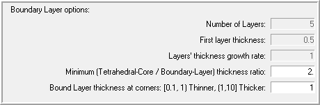
Specify the Boundary Layer options as shown in the following image.
The number of layers, first layer thickness and growth rate have been
established in the BL parameters subpanel and are greyed out here. All
layers will have the same thickness, except for mesh smoothing operations
such as hyperbolic smoothing at corners.
Specify a Minimum (Tetrahedral-Core / Boundary-Layer) thickness ratio value
of 2.
This means that in areas where there is not enough room to grow the nominal
BL (3 layers of 2 each), the boundary layers’ thickness will be reduced so
that the tetrahedral core thickness is at least 2 times the total boundary
layer thickness, except for mesh smoothing operations such as hyperbolic
smoothing at corners, and convex/concave areas.
The last option, Bound Layer thickness at corners, is a coefficient that
controls the hyperbolic growth where walls make an angle. The smaller this
value is, the thinner the total BL thickness in such areas is.
Figure 2.
Now you are ready to generate the Distributed BL Thickness loading. Make sure
that none of the elements specified in the boundary collectors are masked.
If they are masked an error message will indicate that there is a discrepancy
between the total number of elements in the components and the tria3/quad4
elements found. If you have masked elements, you can access the Mask (F5), and
press unmask all.
Click Generate Distributed BL Thickness Ratio.
If the model already contains boundary layer thickness ratios, then a pop-up
message box will ask you if you want to keep such loading or if you want to
delete them. Most of the time you will want to clear the existing boundary layer
thickness ratios; click Yes. In some special cases you
may want to keep them, if more than one loading value is specified at a node,
the minimum value is used when generating the mesh. After a few seconds you will
see a pop-up message indicating the number of distributed boundary layer
thickness values included in collector ^CFD_BL_Thickness.
Click Close in the Generate Boundary Layer
distributed thickness values window.
Click the Tetramesh parameters subpanel.
There are three different tetrameshing algorithms available. Select
Optimize Mesh Quality. For a detailed explanation of
each option, please refer to the online help.
Set the tetrahedral core growth rate to
Interpolate.
This avoids the problem of generating tetrahedral elements that are too large
at the center of the core mesh.
Click mesh to create the CFD mesh.
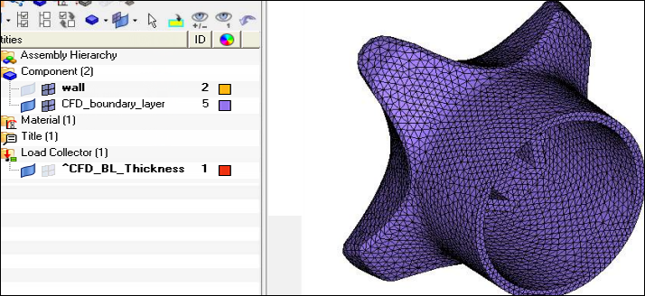
When this task is finished, two collectors are automatically created:
CFD_bl001 and CFD_tetcore001. Figure 3.
Click return to close the panel.
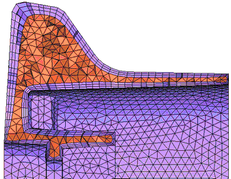
Mask Elements to Inspect the Boundary Layers’ Thickness on Thinner Areas
Access the Mask panel by using the shortcut key F5.
Select elements to be masked.
Click mask.
The following images illustrate how BL interference has been avoided by
reducing the BL thickness.Figure 4.
Generate a Pure Tetrahedral Mesh for Moldflow
The mesh needs to consist of tetrahedral elements only. This was accomplished by
generating tetras directly in the boundary layer. However, if you need to split
penta / wedge elements into tetras, use the procedure below.
Click Mesh > Edit > Elements > Split Elements.
Select the solid elements subpanel.
Set the switch to split into tetras.
Select elems > by collector > wall.
Click split.
Now you have a mesh consisting of tetrahedral elements
only.
Summary
The objective of this tutorial is to illustrate how you can generate very thin
boundary layers without interference.
However, such thin boundary layers can lead to element with a high aspect ratio if
the size of the surface mesh is not small enough. If you need to limit the
tetrahedral elements’ aspect ratio (for example, < 5), then you need to use a
fine enough mesh on the wall component so that thin boundary layers do not produce
high aspect ratio elements. For example, in this case, the minimum value of tetra
collapse of all tetrahedral core elements was 0.2, but after you split the BL penta
/ wedge elements into tetras, the minimum value of tetra collapse of all tetrahedral
elements becomes 0.04. This occurs because the BL penta elements are thin compared
to their triangular face area size.
HyperMesh allowed you to generate high-quality boundary
layer meshes on parts with very thin walls. To accomplish this you first need to use
the utility Generate Distributed BL Thickness Ratio to generate load collector
^CFD_BL_Thickness. This load collector is then used when you enable distributed
thickness. The mesh is very smooth and is of excellent quality.
 , on
the Standard toolbar.
, on
the Standard toolbar.
 quad
elements. You will generate boundary layers on all the surface elements
contained in the collector named wall.
quad
elements. You will generate boundary layers on all the surface elements
contained in the collector named wall.