PAM-CRASH 2G Connector Types
Supported PAM-CRASH 2G connector types and property scripts.
Connector Types
- PAM-CRASH 2G plink (connector position)
- Creates a PLINK element. The PLINK is created at the connector location.
- This realization also uses the prop_plink.tcl1 property script.
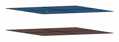
Figure 1.CFG pamcrash2g 1 plink (connector position) *filter spot *head *body 0 mass 5 2 *post prop_plink.tcl - PAM-CRASH 2G plink (middle of the gap)
- Creates a PLINK element. The PLINK is created at the center location between the two components and is offset from the connector location.
- This realization also uses the prop_plink.tcl1 property script.
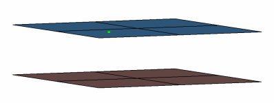
Figure 2.CFG pamcrash2g 2 plink (middle of the gap) *filter spot *head *body 0 mass 5 1 *post prop_plink.tcl - PAM-CRASH 2G bolt (spider)
- Creates an RBODY element. The body element projects and connect to the nodes of the
adjoining shell elements.
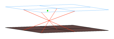
Figure 3.CFG pamcrash2g 54 bolt (spider) *filter bolt *style bolt 1 *head *body 0 rigidlink 1 1 - PAM-CRASH 2G link
- Creates LLINK elements. The LLINK elements are created along the line connector.
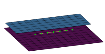
Figure 4.CFG pamcrash2g 55 llink *filter seam *style parallel 1 *head *body 0 rod 5 1 *post prop_llink.tcl - PAM-CRASH 2G adhesives(contact)
- This realization creates rows of HEXA and PENTA elements for the body. The HEXA and PENTA elements project and connect to the adjoining shell/solid elements by touching them.
- The realization uses the prop_pam_rad_adhesives.tcl2 property script.
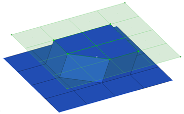
Figure 5.CFG pamcrash2g 56 adhesives (contact) *filter area *style adhesive 1 *head *body 1 hex8 1 1 penta6 1 1 *post prop_pam_rad_adhesives.tcl - PAM-CRASH 2G hexa (adhesive-shell gap)
- Creates a row of hexa elements for the body. The hexa elements are projected so that they touch the elements of the connecting components.
- This realization uses the prop_acm_adhesives.tcl3 property script.
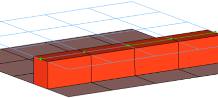
Figure 6.CFG pamcrash2g 57 hexa (adhesive - shell gap) *filter seam *style continuous 2 *head *body 0 hex8 1 1 *post prop_pam_adhesives.tcl - PAM-CRASH 2G hexa (adhesive)
- Creates a row of hexa elements for the body and numerous RBE2/RBE3 elements for the
head. The head elements project and connect to the nodes of the adjoining elements. If
there is a direct normal project then RBE2 element will be created, if there are only
non-normal projections then RBE3 elements will be created. The hexa elements are
projected so that they touch the elements of the connecting components.
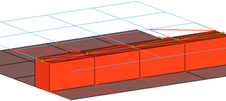
Figure 7.CFG pamcrash2g 58 hexa (adhesive) *filter seam *style continuous 3 *head rbe3 1 0 rigid 1 0 *body 0 hex8 1 1 - PAM-CRASH 2G hexa (tapered T)
- Intended to be used for t-cases. The size and exact position can be defined
thickness dependent, or the exact dimension and position parameters can be given.
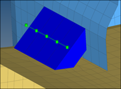
Figure 8.CFG pamcrash2g 105 hexa (tapered T) *filter seam *style continuous 6 *head *body 0 hex8 1 1
Property Scripts
- prop_plink.tcl
This script is called while creation of PLINK– custom config welds in the Spot panel inside PAM-CRASH 2G user interface.
This script does the following tasks:- Organizes the PLINK weld elements created during realization process into C_PLINK_PSCRIPT_<id1_id2> component with the PART_LINK card image associated to it. The id1 and id2 shown above refers to the ids of the link components with which the connector is connected to.
- Creates the M_PLINK_PSCRIPT_<id1_id2> material collector, with the MAT_LINK card image associated with it. This material collector is referenced in the above created component containing the PLINK weld elements.
- Updates the various attributes to the above created material/ property cards.
- prop_pam_rad_adhesives.tclThe script performs the following tasks:
- Creates TYPE2 interfaces (groups) with the names ADHESIVES_CONTACTS_PID_=_#, which reference the independent/dependent links' main sets, and the nodes' slave sets (# is the ID of the links).
- Organizes the link entities (components, and so on) into sets with the names MASTER_PART_SET_PID, which in turn are referenced by the above interface groups (# is the ID of the link entity).
- Organizes the solids' nodes on links into sets with the names SLAVE_NODE_SET_PID_=_#, which in turn are referenced by the above interface groups (# is the ID of the link entity).
- Creates and assigns a property with the name Adhesive_Solid_Property and the card image P43_CONNECT to the solid component.
- Creates and assigns a material with the name Adhesive_Solid_Material and card image M59_CONNECT to the solid component.
- Creates a Failure Model with the name Failure_CONNECT_# and card image FAIL_CONNECT. The curves Adhesive_Solid_Material_YsvsNormalElong and Adhesive_Solid_Material_YsvsTangentialElong are required for the material definition.
Note: For Radioss versions less than Block100 (Block51 and Block90), HyperMesh creates a property definition with the P14_SOLID card image, and a material definition with the M1_ELAS card image. - prop_acm_adhesives.tclThe script performs the following tasks:
- Organizes the HEXA elements and nodes into a component with the name ADHESIVES_#_@ (# is the entity ID of the independent link and @ is the entity ID of the dependent link).
- Creates groups with the names ADHESIVES_CONTACTS_PID_=_#, which reference the independent/dependent links' main sets and the nodes' slave sets (# is the ID of the links).
- Organizes the link entities (components, and so on) into a set with the name MASTER_PART_SET_PID_=_#_parts, which is referenced by set MASTER_PART_SET_PID_=_#, which in turn is referenced by above link group (# is the ID of the link entity).
- Organizes the solids' nodes on links into a set with the name SLAVE_NODE_SET_PID_=_#_nodes, which is referenced by the set SLAVE_NODE_SET_PID_=_#, which in turn is referenced by the above link group (# is the ID of the link entity).
Note: The names of the dependent links node sets are SLAVE NODE SET PID_=_#_nodes and SLAVE NODE SET PID_=_#.