Supported OptiStruct connector types and property
scripts.
OptiStruct Sealing
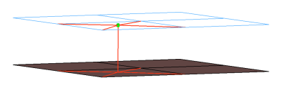
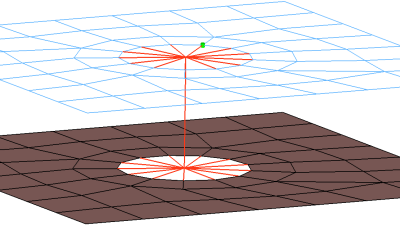
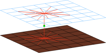
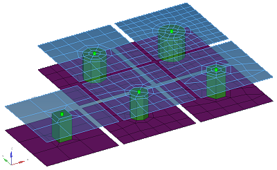
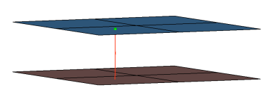
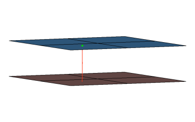
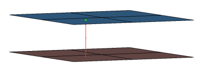
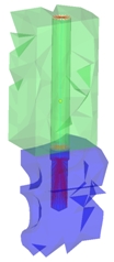
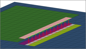
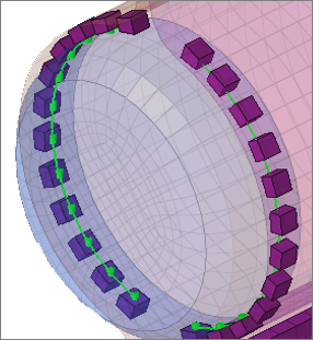
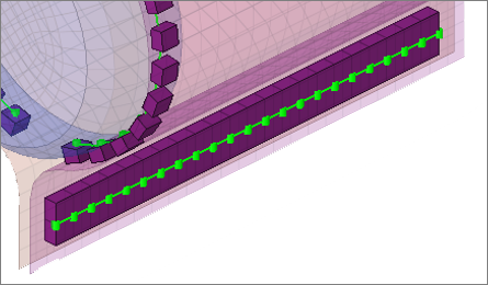
Creates RBE3 elements for the head and CBUSH element for the body. The head elements
project and connect to the nodes of the adjoining shell elements. Figure 1.
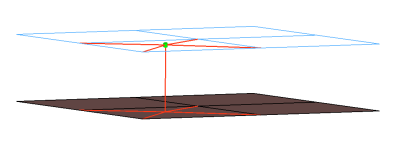
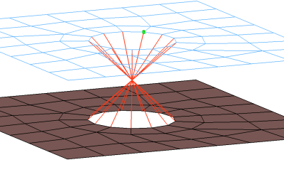
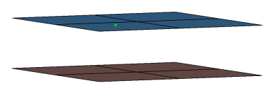
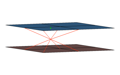
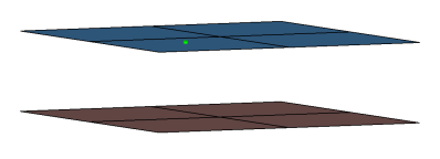
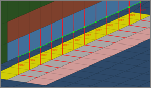
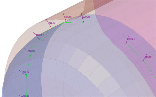
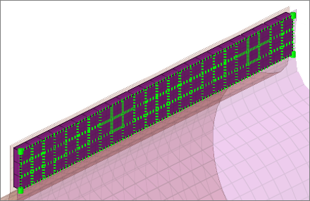
Creates RBE2 elements for the head and CBUSH element for the body. The head elements
project and connect to the nodes of the adjoining shell elements. Figure 2.
CFG optistruct 6 bush
*filter spot
*head
rigidlink 1 1
*body 0
spring 6 1
cfg_optistruct_6_bush
OptiStruct rbe3 (load transfer)
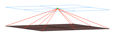
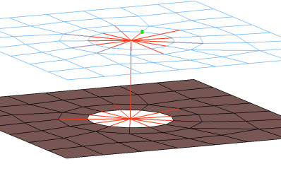
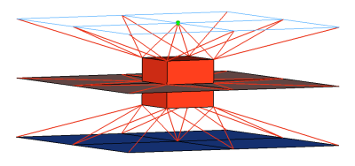
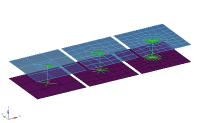
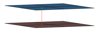
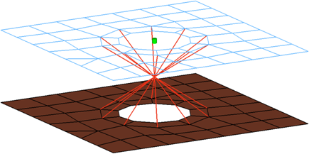
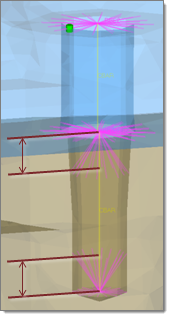
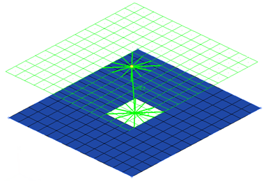
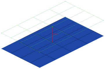
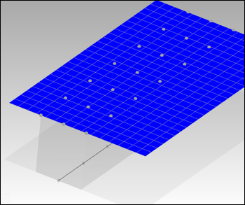
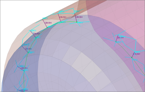
Creates RBE3 elements for the body. The degrees of freedom are constrained in the
x, y, z for the dependant nodes. Figure 3.
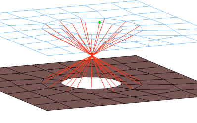
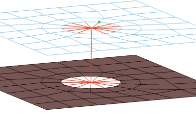
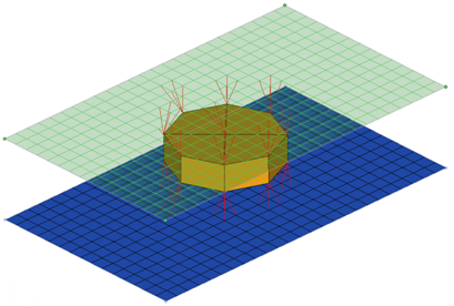
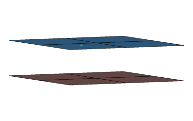
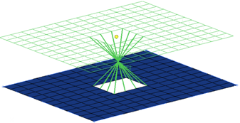
Creates a single RBE2 element for the body. The element projects and connects to the nodes
of the adjoining shell elements which form the hole and also the nodes which form the
washer layer. The connector location can either be on the edge of the hole, center of
the hole, midpoint in between the two holes or on the second row of nodes which form
the washer layer. Figure 4.
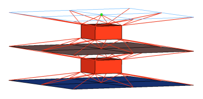
Creates RBE2 elements for the head and CBAR element for the body. The head elements
project and connect to the nodes of the adjoining shell elements which form the hole
and also the second row of nodes which form the washer layer. The connector location
can either be on the edge of the hole, center of the hole, midpoint in between the two
holes or on the second row of nodes which form the washer layer. Figure 5.
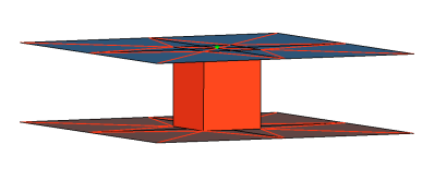
Creates RBE2 elements for the head and the body. The head elements project and connect to
the nodes of the adjoining shell elements which form the hole. The connector location
can either be on the edge of the hole, center of the hole, midpoint in between the two
holes or on the second row of nodes which form the washer layer. Figure 6.
Creates RBE2 elements for the head and CBAR element for the body. The head elements
project and connect to the nodes of the adjoining shell elements which form the hole.
The connector location can either be on the edge of the hole, center of the hole,
midpoint in between the two holes or on the second row of nodes which form the washer
layer. Figure 7.
Creates a many individual RBE2 elements. The element projects and connect to the nodes of
the adjoining shell elements which form the hole, the RBE2 elements are joined at the
midpoint of the bolted connection. The connector location can either be on the edge of
the hole, center of the hole, midpoint in between the two holes or on the second row
of nodes which form the washer layer. Figure 8.
Creates RBE2 elements for the head and the body. There are two individual RBE2 elements at
the head of the connection, one to connect to the inner row of nodes, the other to
connect to the washer layer nodes. The connector location can either be on the edge of
the hole, center of the hole, midpoint in between the two holes or on the second row
of nodes which form the washer layer. Figure 9.
Creates RBE2 elements for the head and the body. There are two individual RBE2 elements at
the head of the connection, one to connect to the inner row of nodes, the other to
connect to the washer layer nodes. The RBE2 head element that connects to the washer
layer nodes only connects to every other node on the washer layer. The connector
location can either be on the edge of the hole, center of the hole, midpoint in
between the two holes or on the second row of nodes which form the washer layer. Figure 10.
Creates RBE2 elements for the head and body. The head elements project and connect
to the nodes of the adjoining shell elements which form the hole and also the second
row of nodes which form the washer layer. The connector location can either be on the
edge of the hole, center of the hole, midpoint in between the two holes or on the
second row of nodes which form the washer layer. Figure 11.
Creates RBE2 elements for the head and body. The head elements project and connect
to the nodes of the adjoining shell elements which form the hole and also the second
row of nodes which form the washer layer. The head only connects to every other node
on the washer layer. The connector location can either be on the edge of the hole,
center of the hole, midpoint in between the two holes or on the second row of nodes
which form the washer layer. Figure 12.
Creates RBE2 elements for the head and the body. The head elements project and
connect to the nodes of the adjoining shell elements which form the hole. The
connector location can either be on the edge of the hole, center of the hole, midpoint
in between the two holes or on the second row of nodes which form the washer layer.
The degrees of freedom are constrained in the x, y, z, rot x, rot z for the dependant
nodes.
This realization also uses the prop_hinge.tcl1 property script. Figure 13.
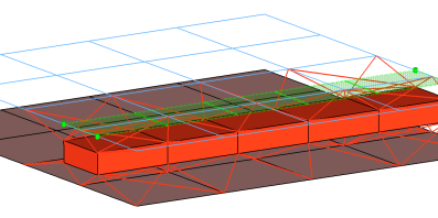
Creates hexa element with RBE3 elements projecting and connecting to the
surrounding shell elements. This realization uses the shell thickness to calculate the hexa
offset from the shell elements. In the case where the model is a 3T connection, the acm
(equivalenced-(T1+T2)/2) realization will join the hexa elements.
This realization also uses the prop_nastran_acm.tcl3 property script. Figure 16.
Creates hexa element with RBE3 elements projecting and connecting to the
surrounding shell elements. This realization uses the shell thickness to calculate the hexa
offset from the shell elements. In the case where the model is a 3T connection, the acm
(detached-(T1+T2)/2) realization will not join the hexa elements.
This realization also uses the prop_nastran_acm.tcl3 property script. Figure 17.
Creates hexa element with RBE3 elements projecting and connecting to the
surrounding shell elements. This realization does not use the shell thickness to calculate
the hexa offset, therefore the hexa will project and be touching the shell elements.
This realization also uses the prop_nastran_acm.tcl3 property script. Figure 18.
This realization creates one hexa cluster per connector and realizes a node to node
connection to the linked shell meshes by adjusting it (shell coating). Different
patterns are available. This is driven by the number of hexas. The appearance can be
influenced via the diameter and the washer layer activation. Figure 19.
This realization prepares a circled shell mesh from a certain number of
segments for each link, so the mesh is adjusted to a rigid element created with the
independent node centered in the circular arranged dependent nodes. The independent nodes
themselves are connected by an additional rigid element.
Different numbers of elements lead to a different pattern. In addition, the appearance can
be influenced via the diameter and the washer layer activation. Figure 20.
This realization type consolidates several ACM definitions into one general, flexible ACM
definition. Besides mid thickness, constant thickness and maintain gaps, the definition of
several coats with different hexa pattern is available.
The realization also uses the prop_nastran_acm.tcl3 property script. Figure 21.
This realization supports Lap-joints and creates PENTA element for the body. Surrounding
shell/solid elements are projected and connected with RBE3 elements. This realization
supports the creation of PENTA elements on one side or on both sides of the joint, and
provides a fitted/equilateral option for the PENTA creation. Figure 22.
This realization supports T-joints and creates PENTA element for the body. Surrounding
shell/solid elements are projected and connected with RBE3 elements. This realization
supports the creation of PENTA elements on one side or on both sides of the joint, and
provides a right-angled option. Figure 23.
This realization supports Butt-joints and creates PENTA element for the body. Surrounding
shell/solid elements are projected and connected with RBE3 elements. This realization
supports the creation of PENTA elements on one side or on both sides of the joint. The
non-normal option needs to be ON/Active for this realization. Figure 24.
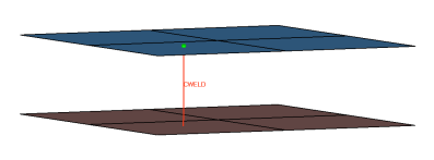
Creates RBE3 element for the head and zero length CELAS1 element for the body. The head
elements project and connect to the nodes of the adjoining shell elements. The degrees
of freedom are constrained in the x, y, z, rot x, rot y, rot z for the dependant
nodes. Figure 34.
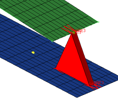
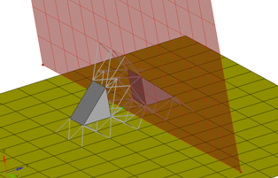
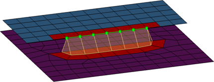
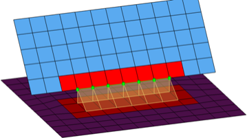
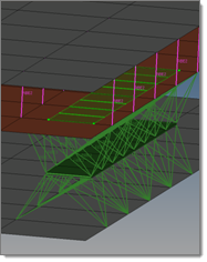
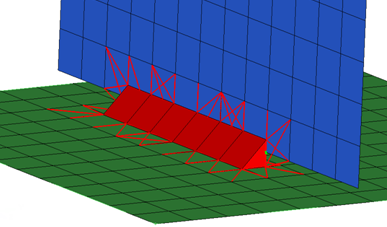
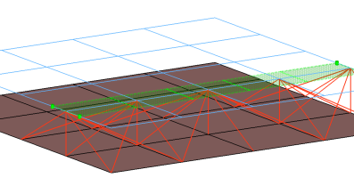
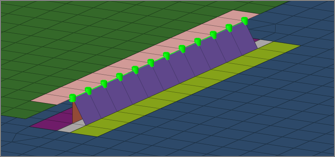
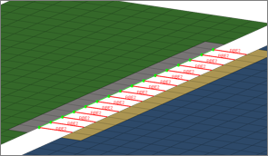
Creates a quad row with tria caps at the seam ends. In addition, a certain
pure quad element pattern is created around the seam elements (shown here in red). These
elements normally get imprinted into the shell links. The exact geometry of the seam can be
influenced by certain attributes in the Seam panel.
This realization is mainly intended to be used for lap welds.
Note: You can revert the
direction of quad seam connectors during the next realization by activating the
reverse direction check box in the Seam panel.
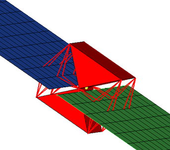
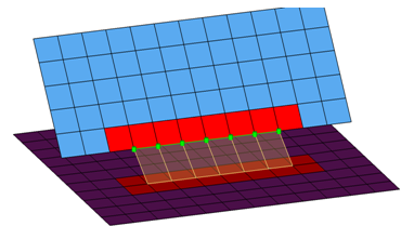
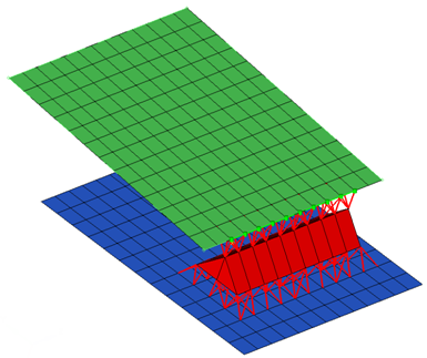
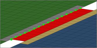
Creates a quad row with tria caps at the seam ends. In addition, a certain pure quad
element pattern is created around the seam elements, shown here in red. These elements
normally get imprinted into the shell links. The exact geometry of the seam can be
influenced by certain attributes in the Seam panel.
This realization is mainly intended to be used for lap welds.
Note: You can revert the
direction of quad seam connectors during the next realization by activating the
reverse direction check box in the Seam panel.
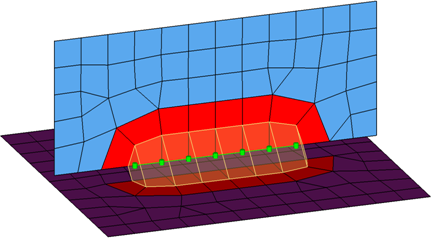
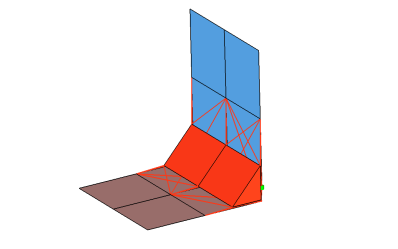
Creates two quad rows-the first one perpendicular to the opposite shell link, and the
second one with a certain angle to the first one. In addition, a certain pure quad
element pattern is created around the seam elements, shown here in red. These elements
normally get imprinted into the shell links. The exact geometry of the seam can be
influenced by the angle value.
This realization is can be used for both lap- and T-welds.
Note: You can revert the
direction of quad seam connectors during the next realization by activating the
reverse direction check box in the Seam panel.
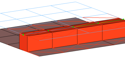
Creates one quad row under a certain angle. The angle is measured between the quad row and
the perpendicular projection from the free edge to the opposite shell link. In
addition, a certain pure quad element pattern is created around the seam elements,
shown here in red. These elements normally get imprinted into the shell links. The
exact geometry of the seam can be influenced by the angle value.
This realization is can be used for both, lap- and T-welds.
Note: You can revert the
direction of quad seam connectors during the next realization by activating the
reverse direction check box in the Seam panel.
Creates penta elements with RBE3 elements projecting and connecting to the surrounding
shell elements. This realization supports many different use cases, including T-joint,
angled T-joint, lap joint and butt joint. Figure 39.
Creates a row of hexa elements for the body and numerous RBE2/RBE3 elements
for the head. The head elements project and connect to the nodes of the adjoining shell
elements. If there is a direct normal project then an RBE2 elements will be used, if there
are only non-normal projections then RBE3 elements will be created. The hexa elements are
projected so that they touch the shell elements of the connecting components.
This realization also uses the prop_nastran_acm.tcl3 property script.Figure 40.
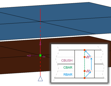
Creates 1D elements that are constructed out of existing RBAR, CBAR, and CBUSH
elements. The outer extensions represent the thicknesses of the outer shell elements. The
inner nodes of the RBAR element are connected to the shell elements, whereas the inner nodes
of the CBAR elements are coincident to the shell nodes only. CBUSHes are created between the
appropriate connected and coincident nodes. Each outer node connects one CBAR and one RBAR.
Each HLOCK connection gets its own coordinate system which has a z-axis that is collinear to
the HILOCK direction. All affected nodes are assigned to the coordinate system. The
coordinate system is taken into account for the DOF definition of the CBAR elements, for the
stiffness calculation of the CBUSH elements, and for the DOF of the node constraint.
This realization uses shell properties and materials (PSHELL or PCOMP) and a HILOCK
material that you select to calculate the exact position of the outer nodes and the
stiffness of the PBUSH elements.
This realization also uses the prop_opt_nas_hilock.tcl6 property script.
For a more detailed examination of the HiLock realization, refer to Special Realization
Types. Figure 45.
Creates a single RBE2 element for the body. The element projects and connects to the nodes
which form the washer layer. The connector location can either be on the edge of the
hole, center of the hole, midpoint in between the two holes or on the second row of
nodes which form the washer layer. Figure 46.
This realization creates a CBAR element for the bolt shaft, and connects to
the solids' nodes with numerous RBE2 based on the given bolt/hole parameters. It also,
connects two solids through holes, or it connects one solid through a hole with a solid
blind hole.
This realization uses the prop_stepboltholes.tcl7 property script. Figure 47.
Connects two solids through holes or connects one solid through a hole with a solid blind
hole. A thread length can be defined to define the dimensions of the rigid elements
connecting the bolt shaft models as a bar. Figure 48.
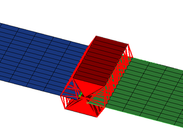
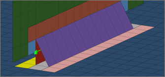
This realization type is used for modeling roll hemmings, where the outer shell is bent
around the inner shell. The inner shell is connected to the outer shell on one side
with simple hexa adhesive, and the other side is connected with RBE2 elements. A
definable orientation node decides which side the hexa adhesive should be used. This
seam realization type is capable of connecting three layers that contains two
components. Figure 49.
This realization supports Lap-joints and creates PENTA element for the body. Surrounding
shell/solid elements are projected and connected with RBE3 elements. This realization
supports the creation of PENTA elements on one side or on both sides of the joint, and
provides a fitted/equilateral option for the PENTA creation. Figure 50.
This realization supports T-joints and creates PENTA element for the body. Surrounding
shell/solid elements are projected and connected with RBE3 elements. This realization
supports the creation of PENTA elements on one side or on both sides of the joint, and
provides a right-angled option. Figure 51.
This realization supports Butt-joints and creates PENTA element for the body. Surrounding
shell/solid elements are projected and connected with RBE3 elements. This realization
supports the creation of PENTA elements on one side or on both sides of the joint. Figure 52.
Creates a row of hexa/penta elements for the body and numerous RBE2/RBE3
elements for the head. The head elements project and connect to the nodes of the adjoining
shell elements. If there is significant curvature in the area connector then penta elements
will be created, otherwise hexa elements will normally be created. If there is a direct
normal project then an RBE2 elements will be used, if there are only non-normal projections
then RBE3 elements will be created.
This realization also uses the prop_nastran_acm.tcl3 property script. Figure 54.
This realization uses the prop_opti_gap.tcl
property script.
OptiStruct bolt (collapse rigid)
This realization creates a single RBE2 element for the body. The element projects and
connects to the nodes of the adjoining shell/solid elements which form the hole. Figure 57.
Serves and realizes t-welds, lap-welds and butt-welds simultaneously. The weld
type is identified automatically based on the orientation of the links to each other.
The dimensions and property for all heat affected zones (HAZ) can be defined
separately.
Normal directions of quad weld elements and HAZ elements can be controlled.
An edge treatment can be defined for t-welds and butt-welds to move the edge a precise
distance from the opposite link.
Serves and realizes t-welds, lap-welds and butt-welds at the same time. The
weld type is identified automatically based on the orientation of the links to each
other.
The dimensions and property for all heat affected zones (HAZ) can be defined
separately.
An edge treatment can be defined for t-welds and butt-welds to move the edge a precise
distance from the opposite link.
This realization creates rows of HEXA elements for the body. The HEXA elements
project and connect to the adjoining shell/solid elements by touching them.
This realization uses the prop_opt_tie_contacts.tcl9 post script. Figure 64.
Creates hexa elements between shell and/or solid elements in order to connect
them using a tie contact definition. The hexa element nodes will project and touch the shell
and/or solid element faces. During the realization, a default tie contact and referencing
main and secondary sets are created; unless defined differently, the hexas are assigned a
default property and material, and are organized into a component with the same name base as
the property.
The default tie contact and material parameters can be changed in the files below this
path: ..\Altair\2021.2\hm\scripts\connectors\Hexa_Tie\optistruct\.
Note: IDs, names, and card
type cannot be changed.
Creates bush (CBUSH) elements between shell and/or solid elements in order to
connect them using a tie contact definition. The bush element nodes will project and touch
the shell and/or solid element faces. During the realization, a default tie contact and
referencing main and secondary sets are created; unless defined differently, the bushs are
assigned a default property, and are organized into a component with the same name base as
the property. If no specific bush coordinate system is defined, the bush elements are
defined with a vector x1, x2, and x3 normal to it.
The default tie contact and material parameters can be changed in the files below this
path: ..\Altair\2021.2\hm\scripts\connectors\Bush_Tie\optistruct\.
Note: IDs, names, and card
type cannot be changed.
Creates hexa elements between shell and/or solid elements in order to connect
them using a tie contact definition. The hexa element nodes will project and touch the shell
and/or solid element faces. During the realization, a default tie contact and referencing
main and secondary sets are created; unless defined differently, the hexas are assigned a
default property and material, and are organized into a component with the same name base as
the property.
The default tie contact and material parameters can be changed in the files below this
path: ..\Altair\2021.2\hm\scripts\connectors\Hexa_Tie\optistruct\.
Note: IDs, names, and card
type cannot be changed.
Creates bush (CBUSH) elements between shell and/or solid elements in order to
connect them using rigid (RBE3) elements. The bush element nodes will project and touch the
shell and/or solid element faces. Unless defined differently, the bushs are assigned a
default property, and are organized into a component with the same name base as the
property. If no specific bush coordinate system is defined, the bush elements are defined
with a vector x1, x2, and x3 normal to it.
The default property parameters can be changed in the files below this path:
..\Altair\2021.2\hm\scripts\connectors\Bush_Rigid\optistruct\.
Note: IDs, names, and
card type cannot be changed.
Automatic Exclusion of Special Nodes During Rigid Bolt Realization
HyperMesh automatically excludes special nodes as potential
secondary nodes for any rigid bodies created during bolt realization, even though they fall with
the virtual Bolt Cylinder diameter. Nodes that are referred in the constraints are
considered special nodes.
Property Scripts
prop_hinge.tcl
This script is called while creation of HINGE–
custom config welds in the connector bolts panel. This script performs the tasks when
the Systems option is active in the connector Bolt panel (such as “Single System”,”1-
System per layer” or 2- Systems per layer).
This Script Assigns both reference
and analysis systems ID to weld element nodes of each Bolt (Hinge) created during
realization process.
prop_cylinder.tcl
Used while creating bolt (cylinder rigid)
and bolt (cylinder bar) in the Bolt panel (Abaqus,
Nastran, OptiStruct). It
organizes the realized bolt elements into the respective components based upon
the*HEAD and the *BODYinformation of the bolt:
A collector with the name Rigid_M<diameter> is created. This component
contains all of the rigid head elements and the rigid body elements, if
available.
A collector with the name Beam_M<diameter> is created. This component
contains all of the bar2 head elements, if available. This component then gets a
property Beam_M assigned (*BEAMSECTION or PBEAM).
prop_nastran_acm.tcl
This script is used in the Nastran and OptiStruct user profiles
during the creation of the following configurations:
acm – equivalence/detached –(T1+T2)/2, and shell gap custom config welds in the
Spot panel,
seam hexa adhesive and seam hexa (RBE2-RBE3) in the Seam panel, and
Area adhesives in the Area panel.
The script performs the following tasks:
Organizes the realized Solid Hexa weld elements created during realization
process into components with names based on the realization, such as
solid_spot_acm_detached, solid_seam_hexa_adhesive_shell_gap, or
solid_area_hexa_adhesive_shell_gap. Components and the connected RBE’s created as
the *HEAD type are organized into components using similar naming, such as
rbe3_spot_acm_detached, rbe3_seam_hexa_adhesive, or rbe3_area_hexa_adhesive.
This script creates property collectors, again using names based on the
realization such as solid_spot_acm_detached, solid_seam_hexa_adhesive_shell_gap,
or solid_area_hexa_adhesive_shell_gap.
These property collectors are created with the PSOLID card associated with
them, and are referenced in the above created components containing the Solid
Hexa weld elements.
In addition, this script also updates the weights of any RBE3 that is almost
zero, because weight factors close to 0.0 cause Nastran and OptiStruct solvers to
generate incorrect results.
Note: New components and properties will only be created if they do not already
exist; otherwise the existing components and properties are used. For this reason,
comps/props will not always follow the naming conventions given here, because
preexisting ones might already have different names.
Also, when creating
realizations with a mid-thickness option, the naming conventions include the
presence of the mid-thickness. For example, when creating a hexa (RBE2-RBE3)
configuration using a mid-thickness option:
Solid elements will be organized into a Component named solid_seam_
hexa_RBE2_RBE3_mid_thick
RBE3 elements will be organized into a Component named rbe3_seam_
hexa_RBE2_RBE3_mid_thick
RBE2 elements will be organized into a Component named rbe2_seam_
hexa_RBE2_RBE3_mid_thick
Properties will be created with the name solid_seam_
hexa_RBE2_RBE3_mid_thick
Materials will be created with the name solid_seam_
hexa_RBE2_RBE3_mid_thick
prop_cweld.tcl
This script is called while creation of all the CWELD GA-GB and GS– custom config welds in the
Spot panel. Theses include PARTPAT, ELPAT, ELEMID, GRIDID, ALIGN. It performs the
following tasks:
Assigns the attributes to the CWELD weld element created during the realization
process, which is either a rod element [GA-GB] or mass Element [GS] of the types
PARTPAT, ELPAT, ELEMID, GRIDID or ALIGN.
Creates the property collector with the name prop_<id> with the PWELD card
associated with it. This property is referenced to the CWELD element created
during realization.
This script also updates the weld radius value in the CWELD card. The diameter
value is either defined by you on the Spot panel, or is taken from the dvst
(diameter versus thickness) file.
Note: This script is called if the CWELD GA-GB and GS– custom config welds and
shell gap custom config welds across Nastran and
OptiStruct user profiles.
prop_opt_nas_cfast.tcl
This script is called while creation of all the CFAST GA-GB and GS– custom config welds in the
Spot panel. Theses include ELEM, and PROP. It performs the following tasks:
Assigns the attributes to the CFAST weld element created during the realization
process, which is either a rod element [GA-GB] or mass Element [GS] of the types
ELEM or PROP.
Creates the property collector with the name PFAST_<diameter> with the PFAST
card associated with it. This property is referenced to the CFAST element created
during realization.
This script also updates the weld diameter value in the CFAST card. The diameter
value is either defined by you on the Spot panel, or is taken from the dvst
(diameter versus thickness) file.
Note: This script is called for the CFAST GA-GB and GS– custom config welds
across Nastran and OptiStruct user profiles.
prop_opt_nas_hilock.tcl
This script is used while creation of
HILOCK custom config welds in the Spot panel from the Nastran and OptiStruct user profile.
This script does the following tasks:
Organizes the realized 1D weld elements (RBAR, CBAR, CBUSH) created during
realization process into a component named HiLock components.
This script will create the following property collectors:
HiLock_PBAR_<diameter>: This property collector is created with the PBAR
card associated with it. The RBAR elements reference to this property. The
attributes are calculated depending on the used diameter in the Spot panel
during realization.
HiLock_PBUSH_<translational stiffness>_<rotational stiffness>: These
property collectors are created with the PBUSH card associated with them. The
CBUSH elements reference to this property. The attributes are calculated
depending on the HILOCK material you select and the properties and materials
of the connected shells (PSHELL and/or PCOMP).
This script will create the following load collector:
HiLock_SPC6
This load collector is created and the SPCs, which are created for each
HiLock will be moved into this collector.
This script will create the following system collector:
HiLock
This system collector is created and the systems created during the
realizations will be moved into this collector. If the system collector
exists already the new created systems will be moved into the same
collector.
If a HiLock material is not chosen, a default material is created:
HiLock_MAT1
This material will be assigned to PBAR cards, and can be found in the
following folder of the installation directory:
[hm_scripts_dir]/connectors/HiLock_Mats.
The predefined values are:
set E 1.8e+07
set G 4.7e+04
set NU 0.330
set RHO 8.9e-09
set A 1.7e-05.
Note: This script is called if the realization CFG Nastran 111 HILOCK or CFG OptiStruct 111 HILOCK is used.
prop_stepboltholes.tcl
The script performs the following
tasks:
Organizes the CBAR elements into a component with the name HM_Bolt_CBAR.
Organizes the RBE2 elements into a component with the name HM_Bolt_RBE2.
Creates a property with the name HM_PBAR and assigns it the PBAR card
image.
Note: New components and properties will only be created if their are not any
components and properties with the same names that already exist; otherwise the
existing components and properties are used.
2021.2
The script performs the following tasks:
Organizes the CGAP elements into a component with the name Realize2001.
Creates a property with the name PGapProp, and assigns the card image PGAP.
Note: New components and properties will only be created if their are not any
components and properties with the same names that already exist; otherwise the
existing components and properties are used.
prop_opt_tie_contacts.tcl
The script performs the following
tasks:
Creates TIE interfaces (groups) with the name ADHESIVE_HEXA_TIE_CONTACT_PID _#
and the card image TIE. The groups reference the independent/dependent links'
main sets and the nodes' secondary sets (# is the ID of the link components).
Organizes the links' component elements into sets with the name
ADHESIVE_HEXA_MAIN_PART_SET_PID_# and the card image SET_ELEM. The sets are
referenced by the above interface groups (# is the ID of the link component).
Organizes the solids‘ nodes on the links into sets with the name
ADHESIVE_HEXA_SECONDARY_NODE_SET_PID _# and the card image SET_GRID. The sets are
referenced by the above interface groups (# is the ID of the link component).
Creates components with the name ADHESIVE_HEXA_COMP_PID _#_# for the connector
SOLID elements (# is the ID of the link component).
Creates properties with the name ADHESIVE_HEXA_PROP_PID_ #_# and the PSOLID
cardimage, and assigns them to respective SOLID components (# is the ID of the
link component).
Creates a material with the name ADHESIVE_HEXA_MAT_PID _#_# and the card image
MAT1, and assigns it to respective SOLID properties (# is the ID of the link
component).