Multistage Stamping Simulation
Learn how to perform a multistage forming process.
Open the Model
-
In the Open File dialog, navigate to the file in the
tutorials folder in the installation directory in
Program Files\Altair\2021.2.1\InspireForm2021.2.1\tutorials\Numisheet_channel_2005.x_t.
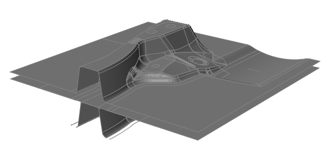
The model should look something like this:
Define the Blank and Material
-
On the Tryout tab, click the Blank icon.

-
On the model, select the blank.
Note: To easily see the blank in the die set, you can hide parts that are blocking the view of the die. To hide a part, select it, right-click, then select Hide. Once you define the blank, unhide the parts.The blank turns red indicating your selection.
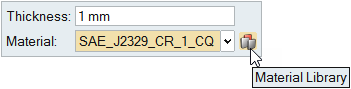
-
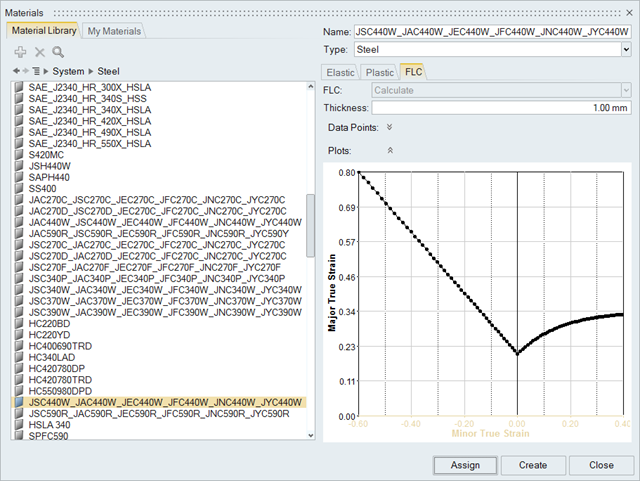
After assigning the blank, in the microdialog that appears, click the ellipses
button to access the Material Library.
-
Click Assign, then Close.
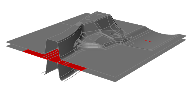
Add a Symmetry Plane to the Model
-
On the Tryout tab, click the
Symmetry icon.

-
Select an edge on a plane as the symmetry plane, and then click to
confirm.
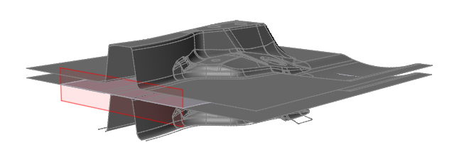
The symmetry plane appears in a red outline.
Set Up the Single Action Draw Operation
-
From the Tryout tab, select the Add
 operation icon.
-
From the Add Operation window, select Single
Action.
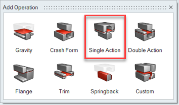 The Single Action operation icon appears on the Tryout ribbon.
 -
To automatically configure the toolset in your model, on the Single Action
operation you just added, click
 .
.

-
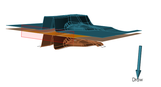
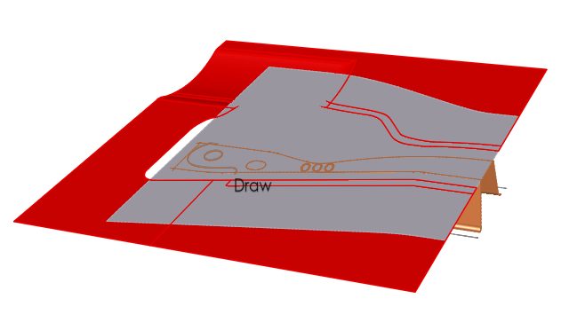
In the guide bar, select the Build tools option, then
click Auto configure.
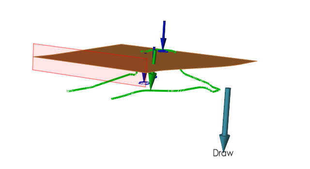
The Build tools option automatically identifies the required tools for the operation: Top Die, Bottom Die, and Bottom Binder. The option also automatically configures the tool set. The model setup should look something like this:
-
In the microdialog, select Maintain Gap
 .
.
-
To preview the forming action of the tryout, on the Single Action icon, click
Preview Tool Motion
 .
.
 An animation of the forming operation is generated for the model.
Add Guidepins to the Model
Add guidepins to the model to support holes in the part and ensure that the blank maintains its correct position during the forming process.
-
Click the Single Action operation icon on the Tryout ribbon.

-
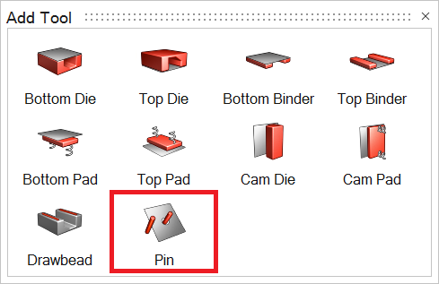
On the secondary ribbon of tools that appears, choose the
Add
tool icon.
-
Click Pin to attach guidepins to the part.
-
On the guidebar, select Attach Tool and choose the tool
which to attach the guidepin. Click again on the part to confirm. The selected
surface appears highlighted in red.
-
Click Pin on the guide bar. Click a surface or line
which to attach the pin.
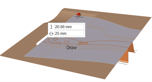
-
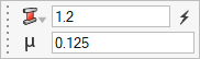
Use the microdialog to configure the height and diameter of the pin.
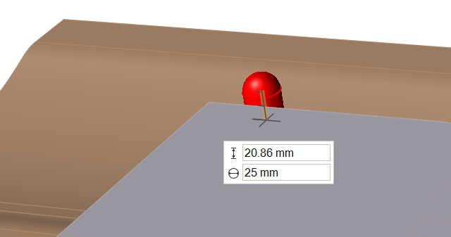 Note: Additional pins must be added individually to the part.
Set Up the Trim and Pierce Operation
-
From the Tryout tab, select the Add
operation icon.
-
From the Add Operation window that appears, select
Trim.
 The Trim operation is added to the ribbon next to the Single Action Draw operation. Once multiple operations are added to the ribbon, a check mark appears in a blue cirlce indicating which operation is current.
 -
To automatically configure the trim lines in your model, on the Trim operation
click .

-
In the guide bar, select the Build tools option, then
click Auto configure.
The Build tools option automatically identifies the trim lines in the model.
 Note: If your model includes a single trim line, the software automatically identifies it. If more than one trim line exists, the longer line is identified as a trim line and the remaining lines are identified as pierce lines.
Set Up the Springback Operation
-
From the Tryout tab, select the Add
operation icon.
-
From the Add Operation window that appears, select
Springback.
 The Springback operation is added to the Tryout ribbon.The blank in your model is automatically identified for the springback analysis.
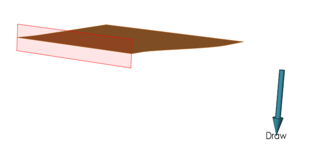
Run the Multistage Simulation
-
From the Tryout tab, Run tools, click Run Analysis
 .
.
-
In the Run Analysis dialog, type in a name, and click
Run.
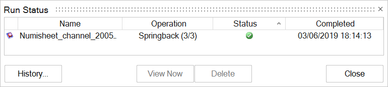
Note: By default, the run name is the model name, and is saved in the run history directory that is specified in the Preferences.The Run Status dialog shows the progress of the simulation. A green check mark indicates that the run is completed.
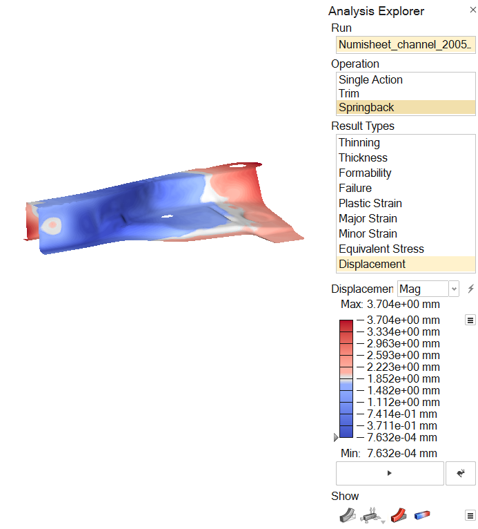
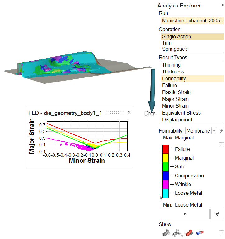
Review the Simulation Results
In the Analysis Explorer, select the following options for the model run and review the results.
-
For Operation, select Single Action. For Result Type,
select Formability.
The results should look something like this:
-
For Operation, select Springback. For Result Type,
select Displacement.
The results should look something like this: