Single Action Draw Simulation with Manual Setup
Learn how to perform a single action draw forming process that is set up with manual tooling and positioning.
Open the Model
-
In the Open File dialog, navigate to the file in the
tutorials folder in the installation directory in
Program Files\Altair\2021.2.1\InspireForm2021.2.1\tutorials\pan.x_t.
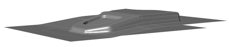
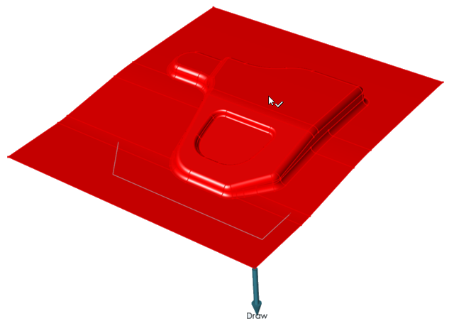
The model should look something like this:
Define the Blank and Material
-
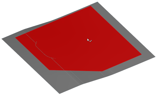
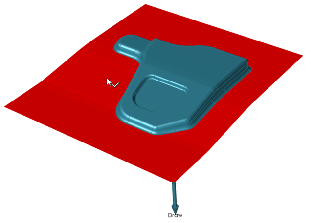
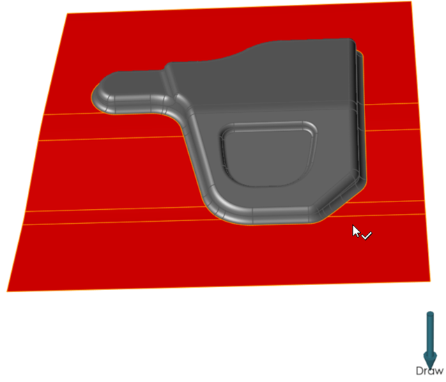
On the Tryout tab, click the Blank icon.

-
On the model, select the blank.
Note: To easily see the blank in the die set, you can hide parts that are blocking the view of the die. To hide a part, select it, right-click, then select Hide. Once you define the blank, unhide the parts.The blank turns red indicating your selection.
Create and Assign a Material Based on Test Data
Create a new material with test data from a .xlsx file.
-
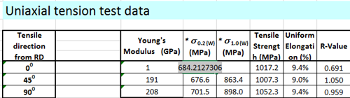
In Microsoft Excel, open and review the file
<installation_directory>\InspireForm2021.2.1\tutorials\Material_Data.xlsx. The data
should look something like this:
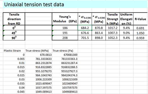
Note: You can copy data from an .xls file and paste it directly into the relevant property fields of the Materials dialog in Inspire Form. -
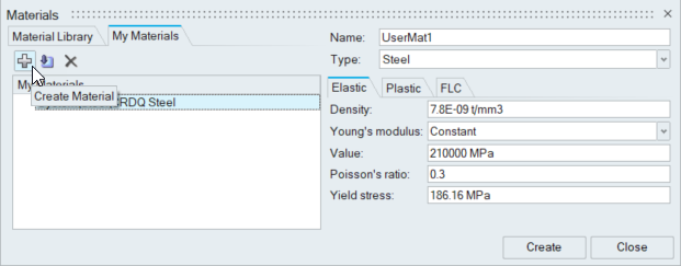
From Inspire Form, on the Tryout tab,
click the Materials icon.

-
Click the Create Material button:
-
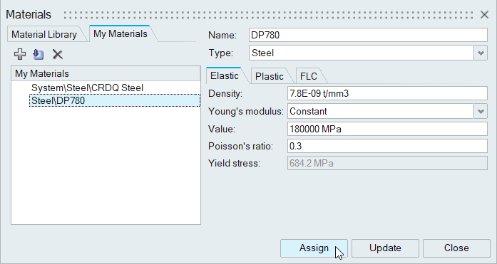
Select the Elastic tab.
-
For Yield stress, enter the value from the .xlsx
file: 684.2MPa
-
For Yield stress, enter the value from the .xlsx
file: 684.2MPa
-
In the first cell of the True Strain column, right-click
and select Clear All.
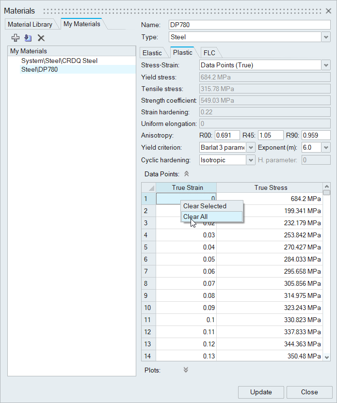
The existing data points are removed. -
Click Assign.
Set Up the Single Action Draw Operation
-
From the Tryout tab, select the Add
 operation icon.
-
From the Add Operation window, select Single
Action.
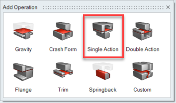 The Single Action operation is added to the Tryout ribbon.
 -
Select the Single Action operation you just added.
The default tool set appears for you to configure.

Configure the Top Die
-
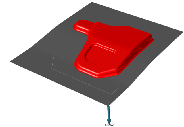
From the tool set, select the Top Die.

-
On the model, select the part for the top die.
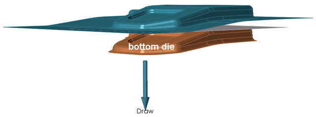
Configure the Bottom Die
-
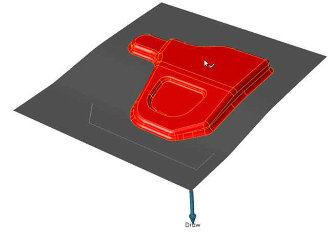
From the tool set, select the Bottom Die.

-
On the model, select the surface of the top die.
The selected surface is highlighted in red, however, this is not the correct surface to offset. To isolate the correct surface, reverse the current selection. -
To reverse the selection, press
Ctrl+R.
The selection of the surface is reversed.
-
Select the new surface.
 A microdialog appears on the model for you to enter a value for the offset. The default value is the thickness of the sheet plus 20%. In this case the value is .1.2 mm.
 -
Click to confirm.
The bottom die is added to the tool set.
Configure the Bottom Binder
-
From the tool set, select the Bottom Binder.

-
On the bottom die of the model, select the surface to offset.
Position the Die Set
 lets you adjust the position of the die set between the
open and closed states. The position of the die set can be defined automatically or
manually.
lets you adjust the position of the die set between the
open and closed states. The position of the die set can be defined automatically or
manually. -
On the ribbon, hover over the single action draw operation that you added to
the anaylsis.

-
Click the Edit Position
icon.
-
Examine the tool set in the closed state: in the three fields of the guide bar,
choose Closed, Auto and
Position.
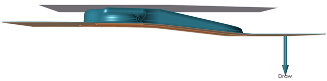
The software automatically positions the tools to their closed state. -
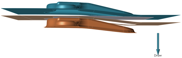
Examine the tool set in the open state: in the three fields of the guide bar,
choose Open, Auto and
Position.
The software automatically positions the tools to their open state. Keep the tools in this state.
Note: A manual option is available for you to manually define the open and closed positions of the tools. -
To preview the forming action of the current tool set, on the Single Action
icon, click Edit Action
 .
.
 An animation of the forming operation is generated for the model. After examining the animation, you can make modifications to the tools as required.
Edit the Tool Parameters
-
From the microdialog, choose edit.
-
To verify the forming action of the tool set, on the Single Action icon, click
Edit Action
.
Run the Tryout Simulation
-
From the Tryout tab, Run tools, click Run Analysis
 .
.
-
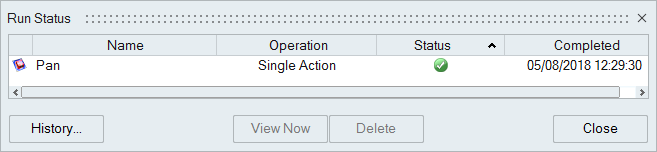
In the Run Analysis dialog, type in a name, and click
Run.
Note: By default, the run name is the model name, and is saved in the run history directory that is specified in the Preferences.The Run Status dialog shows the progress of the simulation. A green check mark indicates that the run is completed.
Review the Simulation Results
The Analysis Explorer lets you choose a variety of results to review. An animation for each result type is included. By default, the results for thinning are displayed on the formed part.
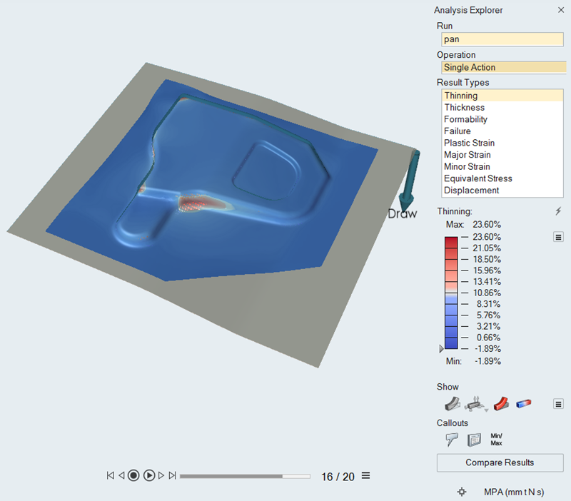
Figure 1. Results for Thinning
-
With the slider below the model, you can review the forming of the model.
- Adjust the results slider to see what areas on your model are under the greatest thinning.
- To animate the results, click the play button. To jump to the first or last step, click the left and right arrow buttons, respectively.
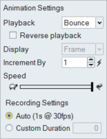
- To adjust the animation settings for playback, display, or speed, on the
slider, click
 .
.
-
To view additional results, from the Analysis Exporer, select a Run, Operation,
and Result Type.
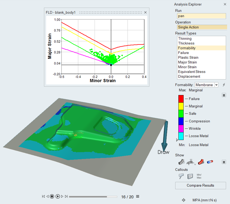 Figure 2. Results for Formability