Loading [MathJax]/jax/output/CommonHTML/jax.js

Generic Heat Exchanger Component

Generic Heat Exchanger Description and Quick Guide

The Generic Heat Exchanger requires that the heat exchanger performance is known. There are several options to specify the performance such as: temperature change, thermal duty, NTU, effectiveness, and the Hs parameter.

Generic Heat Exchanger can be used in Compressible and Incompressible (hydraulic and non-hydraulic) simulations. Currently no phase change is available. The component has four fluid connections, and it models heat exchange between two streams in a network. Heat Exchangers in Flow Simulator come with 4 hidden chambers representing the 4 sides of a heat exchanger. The Generic Heat Exchanger uses Orifice or Effective Area elements (Compressible or Incompressible) in the backend to model restrictions losses (pressure loss) of both flow paths based on user defined loss parameters and characteristic flow area. The Heat addition/removal is calculated based on user inputs for Heat Exchanger Performance curves in Generic Hx module and Q (Heat Addition/Removal) is supplied to Orifice or Effective Area Elements to predict temperatures of the exiting fluids.


Some of the important modeling aspects to be taken care while using heat exchanger components are:
  • The Hot Side circuit must get connected to Line 1 (Indicated by Red Color part of Component Image) & Cold Side circuit get connected to Line 2 (Indicated with Blue Color part of Component Image) as shown in the image below.


  • You can choose to model additional inlet and outlet losses using the separate Discrete Loss/Tube Element upstream and downstream of heat exchanger respectively.
  • The Hot/Cold Side circuit line must be connected with either compressible or Incompressible set of elements. Mixing of elements sets for a Hot/Cold side circuit line is not allowed. Below Table represents some modelling/Allowable scenarios.
Modeling/Allowable Scenarios Flow Simulator Network
Hot Side: Compressible Gases

Cold Side: Compressible Gases

Example: Air to Air Heat Exchanger


Hot Side : Incompressible Liquids

Cold Side : Incompressible Liquids

Example: Fuel Cooled Oil Cooler (FCOC)


Hot Side: Incompressible Liquids

Cold Side: Compressible Gases

Example: Air Cooled Oil Cooler (ACOC)


Hot Side: Compressible Gases

Cold Side: Incompressible Liquids

Example: Air to Liquid Heat Exchanger


Flow Simulator can also be used for Heat Exchanger design. For heat exchanger design a detailed representation of the heat exchanger is required. The example below shows flow elements representing the cold and hot side with thermal network resistors connecting the sides. Heat exchanger performance can be predicted from such a model.


Generic Heat Exchanger Element Inputs

Table of the inputs for the Generic Heat Exchanger Component.

Element Specific Generic Heat Exchanger Component Input Variables
Index UI Name (.flo label) Description
3,11

Cross Sectional Area

(AREA_COLD, AREA_HOT)

Flow area for hot & cold side fluids
4,12

Hydraulic Diameter

(HYD_DIA_COLD, HYD_DIA_HOT)

Hydraulic Diameter for hot & cold side fluids
5,13

Pressure Loss Options

(PLOSS_COLD, PLOSS_HOT)

Options to specify type of pressure loss modelling

  1. Fixed Loss Coefficient
  2. Fixed Total Pressure Drop
  3. Flow vs Delta.P (PTIN – PSEX)
  4. Velocity vs Delta.P (PTIN – PSEX)
  5. Loss Coefficient vs Reynolds Number
6,14

Loss Coefficient

(KLOSS_COLD, KLOSS_HOT)

Incompressible Loss Coefficient
7,15

Delta Total Pressure

(DELTA_PT_COLD, DELTA_PT_HOT)

Total pressure drop across a flow path
T1, T2, T3, T4

Flow vs Delta P

(COLD_DELTA-P, COLD_FLOW,

HOT_DELTA-P, HOT_FLOW)

  • User Specified Curve for Flow vs Delta.P. Delta-P table is the DIFFERENCE between the upstream driving total pressure and downstream sink static pressure
T1, T2, T3, T4

Fluid Velocity vs Delta P (COLD_DELTA-P, COLD_VEL,

HOT_DELTA-P, HOT_VEL)

User Specified Curve for Fluid Velocity vs Delta.P. Delta-P table is the DIFFERENCE between the upstream driving total pressure and downstream sink static pressure
T1, T2, T3, T4

Loss Coefficient vs Reynolds Number

(COLD_KLOSS, COLD_REYN,

HOT_ KLOSS, HOT_REYN)

User Specified Curve for Loss Coefficient vs Reynolds Number.

Reynolds Number= (4.0 * W/ (PERIM * μ))

Where:

  • μ=Dynamic Viscosity
  • W=Mass Flow Rate
  • PERIM=Perimeter=User Input
If Hydraulic Diameter is provided, then:
  • Perimeter=4.0 * A / HYDDIAM
If Hydraulic Diameter or Perimeter is not Provided, Reynolds number is calculated based on Orifice Area:
  • Perimeter=(4.0 * DPI * A)
25 Heat Transfer Options (HOPT)

Options for Modelling Heat Transfer between Hot & Cold side Fluids

  1. Thermal Duty: Heat Input
  2. Hot Fluid Delta.T
  3. Cold Fluid Delta.T
  4. Effectiveness
  5. Effectiveness vs Flow_Rate_Cold vs Flow_Rate_Hot
    1. Effectiveness vs NTU vs Heat Capacity Ratio
    2. Nusselt Number vs RE_Cold vs RE_Hot
    3. Constant hA coefficient value

14) Hs Constant

15) Hs vs Flow_Rate_Cold vs Flow_Rate_Hot

26 Heat Input (QIN) Heat Addition
27 Fluid Delta.T (DELT_T) Delta Total Temperature for Hot (or Cold) Side fluid
28 Effectiveness (EFFECTIVENESS) Effectiveness of Heat Exchanger

T4, T5,

T6

Effectiveness vs Flow_Rate_Cold vs Flow_Rate_Hot

(FLOWRATE_COLD, FLOW_HOT.., EFFECTIVENESS)

3d Table for Effectiveness vs Flow_Rate_Cold vs Flow_Rate_Hot

T4, T5,

T6

Effectiveness vs NTU vs Heat Capacity Ratio

(NTU, ..HEAT_RATIO, EFFECTIVENESS)

3d Table for Effectiveness vs NTU vs Heat Capacity Ratio

T7,

T8,

T9

Nusselt Number vs RE_Cold vs RE_Hot

(NusseltNumber, ReynoldsCold, ReynoldsHot)

3d Nusselt Number vs RE_Cold vs RE_Hot
37 Overall Heat Transfer Coefficient (OVERALL_HTC) Overall Heat Transfer Coefficient Input
29

Type of Configurations

(CONFIG_TYPE)

Heat Exchangers Flow Configurations

  1. Parallel Flow
  2. Counter Flow
  3. Shell & Tube
  4. Cross flow both flows unmixed
  5. Cross flow One fluid mixed
31 Primary hA coefficient (PRI_HA) Htc*Area Coefficient of Primary side fluid
32 Secondary hA coefficient (SEC_HA) Htc*Area Coefficient of Secondary side fluid
30 Number of Shell Passes (NUM_SHELL_PASS) No of Shell Passes for Shell & Tube Hx Configurations
40 Select Mixed Flow (MIXED_FLOW)

Mixed Flow side of HX for Cross flow one side mixed option.

1=Primary, 2=Secondary

41 HX Area (HX_AREA) The total heat exchanger area to be used with the Hs performance parameter
42

Hs Parameter

(HS_PARAMETER)

A Heat Exchanger Performance Parameter

Generic Heat Exchanger Theory Manual

Nomenclature:  
W : Mass flow rate C: Heat Capacity
ρ : Density Q: Heat Addition/Rejection
Cp : Specific Heat Tt: Total Temperature
NTU: Number of Transfer Units  
Subscripts:  
in, up, 1: Upstream station C: Cold
ex, dn, 2: Downstream station H: Hot

Pressure Loss Calculations

There are five different options through which pressure loss across hot or Cold stream can be modelled. They are:

  1. Fixed Loss Coefficient
  2. Fixed Total Pressure Drop
  3. Flow vs Delta.P (PTIN – PSEX)
  4. Velocity vs Delta.P (PTIN – PSEX)
  5. Loss Coefficient vs Reynolds Number

As discussed above, Generic Heat Exchanger uses Orifice or Effective Area elements (Compressible or Incompressible) in the backend to model restrictions losses (pressure loss).

To get more details on pressure drop calculation for:

  • Fixed Loss Coefficient and Fixed Pressure Drop input refer to the Orifice Documentation.
  • Curve based inputs (3,4,5) mentioned above refer to the Effective-Area Orifice Documentation

Heat Transfer Calculations

  1. Heat Input (Qin)

    Tt,ex,Cold=Tt,in,Cold+QinWCold*Cpavg,Cold

    Tt,ex,Hot=Tt,in,HotQinWHot*Cpavg,Hot

  2. Hot Fluid Delta.T

    Q= WHot*Cpavg,Hot (Tt,in,HotTt,ex,Hot)

    Tt,ex,Cold=Tt,in,Cold+QWCold*Cpavg,Cold

  3. Cold Fluid Delta.T

    Q= WCold*Cpavg,Coldt (Tt,ex,ColdTt,in,Cold)

    Tt,ex,Hot=Tt,in,HotQWHot*Cpavg,Hot

  4. Effectiveness

    CHot= ABS(WHot)*Cpavg,Hot

    CCold= ABS(WCold)*Cpavg,Cold

    Cmin=min(CHot, CCold)

    QMax= Cmin*(Th,inTc,in)

    Q= QMax*Effectiveness

    Tt,ex,Cold=Tt,in,Cold+QWCold*Cpavg,Cold

    Tt,ex,Hot=Tt,in,HotQWHot*Cpavg,Hot

  5. Effectiveness vs Flow_Rate_Cold vs Flow_Rate_Hot

    Effectiveness is obtained from User Defined Input for Effectiveness as function Flow_Rate_Cold and Flow_Rate_Hot.

    CHot= ABS(WHot)*Cpavg,Hot

    CCold= ABS(WCold)*Cpavg,Cold

    Cmin=min(CHot, CCold)

    QMax= Cmin*(Th,inTc,in)

    Q= QMax*Effectiveness

    Tt,ex,Cold=Tt,in,Cold+QWCold*Cpavg,Cold

    Tt,ex,Hot=Tt,in,HotQWHot*Cpavg,Hot

  6. Effectiveness vs NTU vs Heat Capacity Ratio

    Effectiveness is obtained from User Defined Input for Effectiveness as function NTU and Heat Capacity Ratio.

    NTU= UACmin

    CRatio= CminCmax

    UA is calculated from Constant user input or from curve specified for Nusselt Number as function of Reynolds Number Cold and Reynolds Number Hot

    UA= Nusselt_Number *KDh

    Effectiveness=1e((1CRatio)NTU0.22e(CRatioNTU0.781))

    CHot= ABS(WHot)*Cpavg,Hot

    CCold= ABS(WCold)*Cpavg,Cold

    Cmin=min(CHot, CCold)

    QMax= Cmin*(Th,inTc,in)

    Q= QMax*Effectiveness

    Tt,ex,Cold=Tt,in,Cold+QWCold*Cpavg,Cold

    Tt,ex,Hot=Tt,in,HotQWHot*Cpavg,Hot

  7. Nusselt Number vs RE_Cold vs RE_Hot

    Nusselt Number is obtained from User Defined Input for Nusselt Number as function of Reynolds Number Cold and Reynolds Number Hot

    UA= Nusselt_Number *KDh

    NTU= UACmin

    Effectiveness=1e((1CRatio)NTU0.22e(CRatioNTU0.781))

    CHot= ABS(WHot)*Cpavg,Hot

    CCold= ABS(WCold)*Cpavg,Cold

    Cmin=min(CHot, CCold)

    QMax= Cmin*(Th,inTc,in)

    Q= QMax*Effectiveness

    Tt,ex,Cold=Tt,in,Cold+QWCold*Cpavg,Cold

    Tt,ex,Hot=Tt,in,HotQWHot*Cpavg,Hot

  8. Constant hA Coefficient value

    CHot= ABS(WHot)*Cpavg,Hot

    CCold= ABS(WCold)*Cpavg,Cold

    Cmin=min(CHot, CCold)

    1UA=(1h*A)Cold+(1h*A)Hot

    NTU Effectiveness Methods:
    1. Cross Flow Unmixed

      Effectiveness=1e((1CRatio)NTU0.22e(CRatioNTU0.781))

    2. Counter Flow

      Effectiveness= 1eNTU(1CRatio)1CRatioeNTU(1CRatio)

    3. Parallel Flow

      Effectiveness= 1eNTU(1+CRatio)1+CRatio

    4. Cross Flow Both Side Mixed

      Effectiveness= 11(1e_NTU)+CRatio1eCRatioNTU1NTU

    5. Cross Flow One Side Mixed

      Cmin is mixed: Effectiveness=1e(1CRatio)(1eCRatioNTU)

      Cmax is mixed: Effectiveness= (1CRatio)(1e(CRatio(1e_NTU)))

      QMax= Cmin*(Th,inTc,in)

      Q= QMax*Effectiveness

      Tt,ex,Cold=Tt,in,Cold+QWCold*Cpavg,Cold

      Tt,ex,Hot=Tt,in,HotQWHot*Cpavg,Hot

  9. Hs Parameter Methods (Constant and vs Hot and Cold Flowrates)

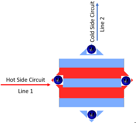
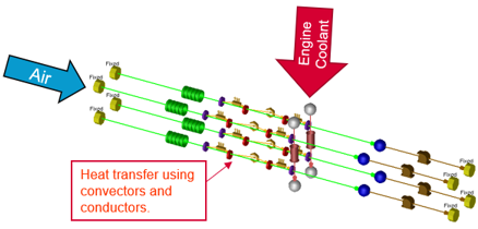
    The Hs parameter is typically used to describe radiators where the hot side is a liquid coolant, and the cold side is air.

    Hs=ABS(WHot)*Cpavg,Hot*(Th,inTh,ex)HXArea*(Th,inTc,in)

    Hs*HXArea*(Th,inTc,in)=ABS(WHot)*Cpavg,Hot*(Th,inTh,ex)=Q

    A heat exchanger effectiveness can be calculated using the Hs parameter.

    Effectiveness=Q / QMax

    QMax= Cmin*(Th,inTc,in)

    Effectiveness=Hs*HXArea*(Th,inTc,in)Cmin*(Th,inTc,in)=Hs*HXAreaCmin

    Q is found using the effectiveness Qmax. The Q is applied to the fluid streams to get the exit temperatures.

    Tt,ex,Cold=Tt,in,Cold+QWCold*Cpavg,Cold

    Tt,ex,Hot=Tt,in,HotQWHot*Cpavg,Hot

Note: Bi-Linear interpolation is employed between the values in the table to determine Y Values. If X-Value is less than its first value entry in the table, the first Y-Value entry is used. If X-Value is greater than its last value entry in the table, the last Y-Value entry is used. Flow Simulator doesn’t do any extrapolation if the values are outside the prescribed input limits.

Generic Heat Exchanger Outputs

The following listing provides details about Generic Heat Exchanger Component output variables.

Name Description Units
PS Static pressure psia, MPa
PT Total pressure psia, MPa
TT Total temperature of fluid deg F, deg K
RE Reynold Number (None)
Rho Density lbm/ft^3, Kg/m^3
CP Specific Heat Btu/(Lbm R), kJ/Kg.K
K Thermal Conductivity Btu/(hr ft R), W/m.K
DVISC Dynamic Viscosity Lbm/(hr ft), N s/m^2
Area Flow Area In2, m2
Heat Mode

Heat Mode Options (An echo of the user input)

  1. Heat Input
  2. Hot Fluid Delta.T
  3. Cold Fluid Delta.T
  4. Effectiveness
  5. Effectiveness vs Flow_Rate_Cold vs Flow_Rate_Hot
  6. Effectiveness vs NTU vs Heat Capacity Ratio
  7. Nusselt Number vs RE_Cold vs RE_Hot
  8. Constant hA coefficient value
(None)
Pri/cold_side_ploss_opt

Options specified for Pressure Loss Modelling for Pri/Cold side

  1. Fixed Loss Coefficient
  2. Fixed Total Pressure Drop
  3. Flow vs Delta.P (PTIN – PSEX)
  4. Velocity vs Delta.P (PTIN – PSEX)
  5. Loss Coefficient vs Reynolds Number

(An echo of the user input)

(None)
Sec/hot_side_ploss_opt

Options specified for Pressure Loss Modelling for Sec/Hot side

  1. Fixed Loss Coefficient
  2. Fixed Total Pressure Drop
  3. Flow vs Delta.P (PTIN – PSEX)
  4. Velocity vs Delta.P (PTIN – PSEX)
  5. Loss Coefficient vs Reynolds Number

(An echo of the user input)

(None)
Q Heat Transferred between Heat Exchanger fluids. BTU/sec, W
Effectiveness Effectiveness of Heat Exchanger (None)
Pri/cold_side_delta.p Delta.PT on Pri/Cold side flow psia, MPa
Sec/hot_side_delta.p Delta.PT on Sec/Hot side flow psia, MPa
Mdot Mass Flow Rate Lbm/s, kg/s
Flow configuration

Heat Exchangers Flow Configurations

  1. Parallel Flow
  2. Counter Flow
  3. Shell & Tube
  4. Cross flow both flows unmixed
  5. Cross flow One fluid mixed

(An echo of the user input)

(None)
Overall conductance(UA) Overall Thermal Resistance BTU/hr.F, W/K
NTU No of Transfer Units (None)
Pri_hA_out Pri/Cold side flow hA Coefficient value BTU/hr.F, W/K
Sec_hA_out Sec/Hot side flow hA Coefficient value BTU/hr.F, W/K