Transient Run Control Parameters
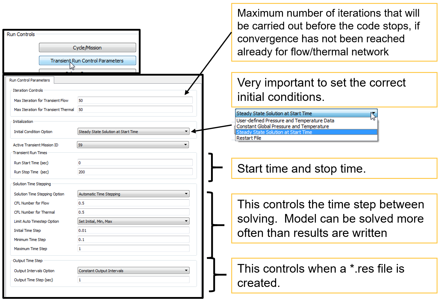
This Panel Consists of Controls that are available for Transient & Quasi Steady runs
Transient Run Control Parameters Overview

Initial Condition Option
| Options | Description |
| User-defined |
The initial conditions for each internal chamber are used at the start time. User must set conditions on each chamber. Results from the GUI’s incompressible initializer are not correct for this. |
| Global |
The initial conditions for each internal chamber are set to this P and T at the start time
|
| Steady State | A steady state solution is run at the start time |
| Restart File |
GUI reads a .res file and saves chamber P, T, MACH etc.
|
Time Stepping Controls
Time steps control settings for solving and output of results. Time steps for solving can be smaller or the same as the output time steps. Time step size is problem dependent. Time steps must be small enough to capture transient accurately. Suggest that time step sensitivity studies be performed
Constant Time Stepping: Simplest method is a constant time step (in seconds). Ok for simple transient.

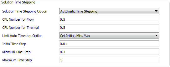
Automatic Time Stepping: Adjusts time step based on CFL number (0 < CFL <= 1) and solver convergence. Solver will bisect timestep if it does not converge. Run will stop if solver does not converge at the minimum timestep. Better for complex transients.


There are two options available to limit “Auto Time step” during the solution, they are
- Set constant Initial, Min, Max data for Time Step
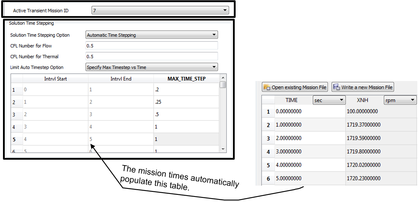
- Specify “Max Timestep vs Time” - sets the maximum timestep at each interval of the mission. A mission must exist in the .flo file and must be selected as the active mission for “Specify Max Timestep vs Time” method

Solve only at Mission times (Quasi Only): Quasi steady state runs can solve at each of the times in the mission.

Wave Speed Estimate (Water Hammer Simulation Only): Wave Speed Estimate for calculating automatic time stepping for water hammer simulations


