Define Layer Properties
This option defines the shield layer properties by either a manual definition in the .pre file or by loading from file.
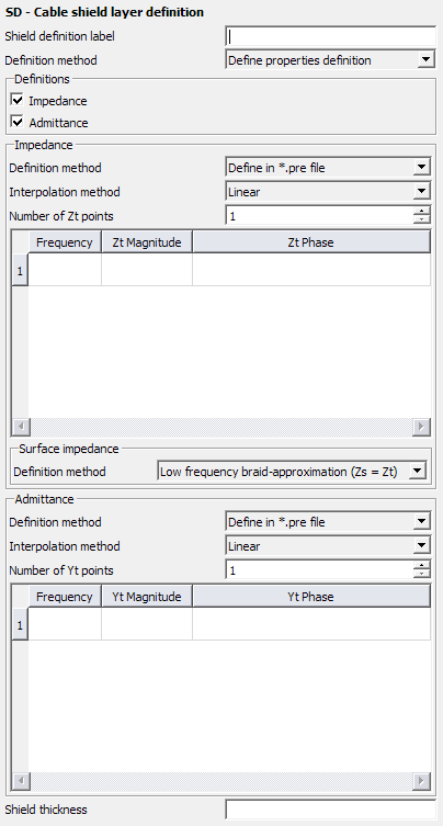
Figure 1. The SD - Cable shield layer definition dialog, set to Define properties definition.
Parameters:
- Shield definition label
- A name for the shield layer definition.
- Impedance
- Select this option to include transfer and surface impedance definition.
- Admittance
- Select this option to include the transfer admittance definition.
- Define in the *.pre file
- The frequency dependent shield parameters based on measured transfer
impedance, surface impedance and transfer admittance data can be specified
in the .pre file.
- Interpolation method
- Choose an interpolation method for the data:
- Default
- Constant
- Linear
- Cubic spline
- Rational (Thiele)
- Number of Zt, Zs or Yt points
- Total number of frequency points.
- Frequency
- The frequency at which the transfer impedance, surface impedance or transfer admittance is specified in the .pre file.
- Zt, Zs or Yt Magnitude
- The magnitude of the transfer impedance, surface impedance or transfer admittance defined in the .pre file.
- Zt, Zs or Yt Phase
- The phase of the transfer impedance, surface impedance or transfer admittance defined in the .pre file.
- Load from file
- The file format used when importing the shield properties from file is described in Load Shield Properties from a .XML File.
- Surface Impedance - Solid (Metallic material)
-
- PEC
- Select this option to set the shield of the filaments to PEC.
- Material label of metallic material
- The label of the material (as defined in the DI card) to be used for the shield.
- Surface Impedance (Zs = Zt)
- Low frequency braid-approximation the data defined for the transfer impedance is also used for the surface impedance definition.