A3 Card
This card realises excitation by a magnetic ring current (TEM-frill) on a segment. It gives an an accurate model of a coaxial feed, but requires both the inner and outer radii.
On the Source/Load tab, in the Sources on
geometry group, click the ![]() Archaic sources
icon. From the drop-down list, click the
Archaic sources
icon. From the drop-down list, click the ![]() Magnetic frill (A3) icon.
Magnetic frill (A3) icon.
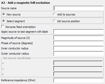
Figure 1. The A3 - Add a magnetic frill excitation dialog.
Parameters:
- New source
- A new source is defined that replaces all previously defined excitations.
- Add to sources
- A new source is defined which is added to the previously defined excitations.
- Select segment
- When this item is selected, the Apply source to last segment with label text box becomes active. This text box is for specifying the label of the segment on which the TEM frill is placed. If more than one segment has this label, the source is applied to the last segment with this label. Alternatively, one may select Set source position to determine the feed segment by specifying the Cartesian coordinates in the Set source coordinates group. The position values are in m and are scaled by the SF card if Modify all dimension related values is checked in the SF card.
- Reverse feed orientation
- The vector of the excitation points in the direction of the segment by default - from the start point to the end point consistent with how the segment was created. When this option is checked, the orientation of the excitation is reversed.
- Magnitude of source
- Magnitude of the voltage source in V.
- Phase of source
- Phase of the voltage source in degrees.
- Inner conductor radius
- Radius of the inner conductor of the coaxial feed.
- Outer conductor radius
- Radius of the outer conductor of the coaxial feed.
- Reference impedance (Ohm)
- The reference impedance of the excitation is used for S-parameter calculations and is the reference impedance used for realised gain calculations. It is also the default reference impedance used to calculate and display the reflection coefficient in POSTFEKO. If this field is empty or 0 in an S-parameter calculation, the value specified at the SP card is used. For realised gain and reflection coefficient calculations, 50 Ohm will be assumed when the field is empty or 0.
As a rule of thumb, the radius of the inner conductor must be the same as the radius of the segment. In addition the outer radius should be 2 to 3 times the size of the inner radius. If an impedance Z is desired, then the following relation can be used to determine the outer radius:
For a 50 coaxial line the outer radius should be equal to 2.3 times the inner conductor radius.