AK Card
This card defines a voltage source to a radiating cable with or without irradiation considered.
On the Source/Load tab, in the Sources on
geometry group, click the ![]() Voltage source
icon. From the drop-down list, click the
Voltage source
icon. From the drop-down list, click the ![]() Voltage on cable (AK) icon.
Voltage on cable (AK) icon.
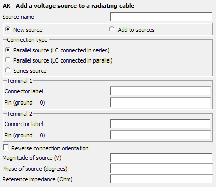
Figure 1. The AK - Add a voltage source to a radiating cable dialog.
Parameters:
- New source
- A new excitation is defined which replaces all previously defined excitations.
- Add to sources
- A new excitation is defined which is added to the previously defined excitations.
- Connection type
- The voltage source can be connected in more than one configuration. The selected configuration influences the placement of an LC load if it is connected between the same pins.
- Terminal 1
-
- Connector label
- The connector label that uniquely identifies the connection of the cable path section.
- Pin (ground=0)
- The pin number identifies the conductor associated with the cable path section as defined by Connector label in the CS card. If the pin is set to 0, the connector pin is connected to ground at the connector.
- Terminal 2
-
- Connector label
- The connector label that uniquely identifies the connection of the cable path section.
- Pin (ground=0)
- The pin number identifies the conductor associated with the cable path section as defined by Connector label in the CS card. If the pin is set to 0, the connector pin is connected to ground at the connector.
- Reverse connection orientation
- By default the positive terminal will be connected to the pin defined at Terminal 1 and the negative terminal of the source will be connected to the pin defined at Terminal 2. When this option is selected the orientation of the source is reversed.
- Magnitude of source
- Magnitude of the voltage source in V.
- Phase of source
- Phase of the voltage source in degrees.
- Reference impedance (Ohm)
- The reference impedance of the excitation is used for S-parameter calculations and is the reference impedance used for realised gain calculations. It is also the default reference impedance used to calculate and display the reflection coefficient in POSTFEKO. If this field is empty or 0 in an S-parameter calculation, the value specified at the SP card is used. For realised gain and reflection coefficient calculations, 50 Ohm will be assumed when the field is empty or 0.