Connection Types
The connection types and orientation of the source and loading must be understood and applied correctly in order to have the desired excitation and loading of the cable bundle.
In all the examples a load (defined with the LC card) and two cable interconnections (defined with the CI card) are defined to illustrate the circuit configuration. These additional elements are not required for the parallel connection, but at least one additional element is required for the series connected source.
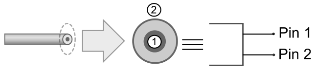
Figure 1. Illustration of a cable, its pin numbering and the schematic terminal pins it represents.
Parallel source (LC connected in series):
The example consists of the following set of elements:
- A parallel connected source where an LC load would be connected in series. The default connection orientation is used (positive terminal of the source is connected to the pin defined at the first terminal).
- An LC load is defined between the two pins.
- Two cable interconnections are defined between the two pins.
The figure below is an illustration of the connection between the two connector pins.
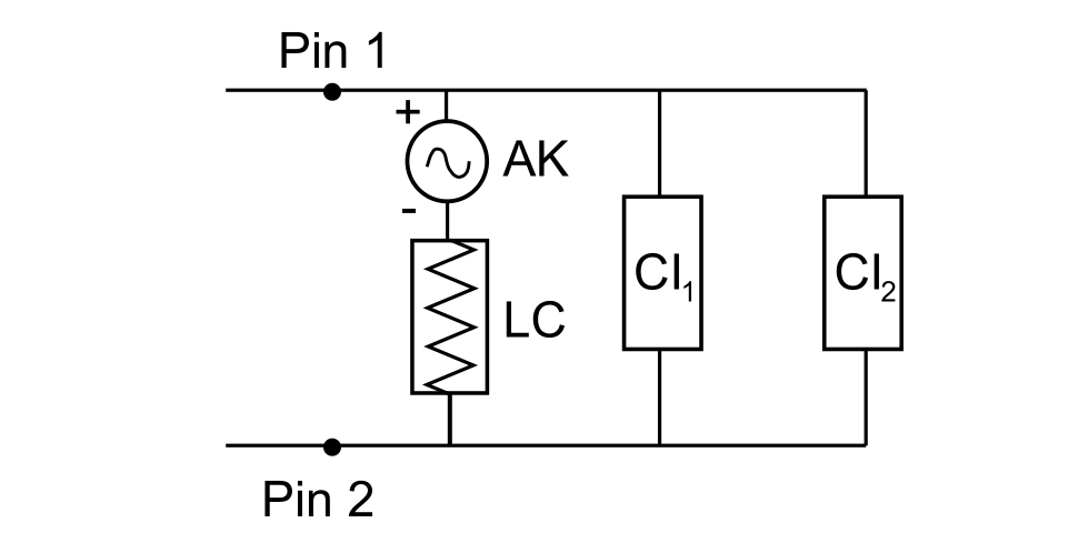
Figure 2. The Parallel source connection type where the LC load is connected in series with the AK source.
Parallel source (LC connected in parallel):
The example consists of the following set of elements:
- A parallel connected source where an LC load would be connected in parallel with the source. The connection orientation has been reversed so that the negative terminal of the source is connected to the pin defined at the first terminal.
- An LC load is defined between the two pins.
- Two cable interconnections are defined between the two pins.
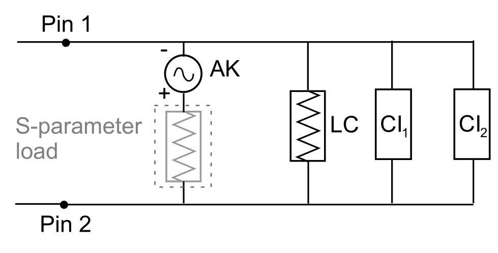
Figure 3. The Parallel source connection type where the LC load is connected in parallel with the AK source.
Series source
The example consists of the following set of elements:
- A series connected source. The connection orientation has been reversed so that the negative terminal of the source is connected to the pin defined at the first terminal.
- An LC load is defined between the two pins.
- Two cable interconnections are defined between the two pins.
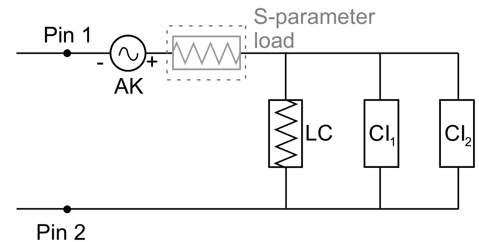
Figure 4. The source is placed in series with everything that is connected at Pin 1.
Series and parallel source
The last example is a more complicated example where two sources are added between the same pins. The example consists of the following set of elements:
- A parallel connected source where an LC load would be connected in parallel with the source. The connection orientation has been reversed so that the negative terminal of the source is connected to the pin defined at the first terminal.
- A series connected source connected to the pin defined by the second terminal of the source defined above. The default connection orientation is used (positive terminal of the source is connected to the pin defined at the first terminal).
- An LC load is defined between the two pins.
- Two cable interconnections are defined between the two pins.
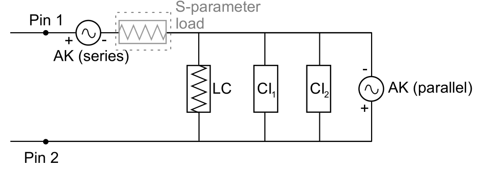
Figure 5. Two sources are placed between the same pins. The one source is connected in parallel and the other in series.