Import Modes from FEST3D File
With this option,impressed forward travelling modes in all waveguides of a multi-port network can be imported from a .fim file.
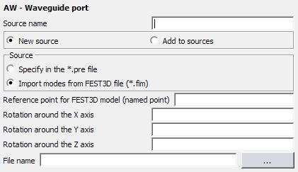
Figure 1. The AW - Waveguide port dialog for importing from a FEST3D file.
Parameters:
- Reference point for FEST3D model (named point)
- A named point indicating the translation of the imported model in the Feko coordinate system. Note that this point must have been previously defined with a DP card.
- Rotation around the X axis
- This specifies the rotation of the imported model around the X axis in degrees.
- Rotation around the Y axis
- This specifies the rotation of the imported model around the Y axis in degrees.
- Rotation around the Z axis
- This specifies the rotation of the imported model around the Z axis in degrees.
- File name
- The name of the .fim file.
In order to model a waveguide port excitation by an impressed mode, the cross section of the waveguide at the port location must be meshed into metallic triangles with a unique label. The propagation direction is given by the unit vector , see the small graphics in the AW card panel above.
In general, specific meshing rules exist in Feko relating the triangular patch size to the wavelength. When meshing the cross section of a waveguide to define a waveguide port, the mesh size must be small enough to capture the field distribution of the highest mode ( , ) which is included in the expansion. Feko checks this automatically and gives a warning for coarse meshes or an error if the mesh size is too large. One must then either refine the mesh just at the port or reduce the maximum mode indices used in the expansion.
- Waveguide ports are available for models containing metallic objects (wires and surfaces and wire/surface junctions, including PO) and dielectrics (solved using the SEP, FEM) or dielectric coatings and thin dielectric sheets.
- Special Green’s functions may not be used in conjunction with waveguide port feeds
- When using waveguide ports, then UTD is not allowed in the same model. Note, however, that in Feko it is possible (using the AR or AP cards) to decompose a model (say a horn antenna in front of a reflector) into different sub-problems. If this approach is followed, then waveguide feeds may be used. See Example_35 in the Scripting Examples guide for an illustration of this decomposition technique.
The reflection coefficient at each waveguide port (S11) is always calculated and available for display in POSTFEKO on an S-parameter graph, even when no S-parameter calculation has been requested. Requesting S-parameters with the SP card is supported for waveguide ports. Multiple ports (active and/or passive) can be present in the model. S-parameters are directly based on the waveguide impedance of the specific mode under consideration. The reference impedance as specified at the SP card is not used for waveguide ports.
Examples for the application of waveguide feeds can be found in the Examples Guide (E-2) and in the Script Examples, example_08 and example_34.
In order to rule out any possible doubts and ambiguities regarding the waveguide mode definitions, we give here the explicit expressions of the modes as used in Feko. This implementation follows closely the conventions in S. Ramo, J. R. Whinnery, and T. van Duzer, Fields and Waves in Communication Electronics, John Wiley & Sons, Inc., 3rd ed., 1994.
Rectangular waveguide expressions
Local Cartesian coordinates are assumed. The factor is omitted for brevity, where β is the complex modal propagation coefficient. In the expressions below, let a be the dimension of the waveguide port in (distance between S1 and S2), and b the dimension of the waveguide port in (distance between S1 and S3). The modal cutoff coefficient is the same for TM- and TE-modes, and is given by,
For transverse electric (TE) modes the axial electric field component vanishes, and the axial magnetic field component for the mode is expressed as,
Circular waveguide expression
Local cylindrical coordinates are assumed with the Z axis on the waveguide axis (S1-S3). The factor is omitted for brevity, where is the complex modal propagation coefficient. The expressions below are valid for the fields inside a circular waveguide, for example, , where is the radius of the waveguide port. is the order Bessel function of the first kind, and denotes the derivative with respect to the argument.
For transverse magnetic (TM) modes the axial magnetic field component vanishes, and the axial electric field component for the mode is expressed as,
for and is the complex amplitude of the impressed mode in and is the rotation angle. The modal cutoff coefficient is the zero of . The remaining field components are,
For transverse electric (TE) modes the axial electric field omponent vanishes, and the axial magnetic field component for the mode is expressed as,
for and is the complex amplitude of the impressed mode in and is the rotation angle. The modal cutoff coefficient is the zero of . The remaining field components are,
Coaxial waveguide expressions
Local cylindrical coordinates are assumed with the Z axis on the waveguide axis (S1-S3). The factor is omitted for brevity, where is the complex modal propagation coefficient. The expressions below are valid for the fields inside a coaxial waveguide, for example, for , where is the radius of the outer conductor and is the radius of the inner conductor of the coaxial waveguide port. and are order Bessel function of the first and second kind, respectively and and denote the derivatives with respect to the argument.
The fundamental mode in a coaxial waveguide is a TEM wave and propagates with .The axial electric and magnetic field components are zero for a TEM-mode, and the transverse field components have a static field distribution,
is the complex amplitude of the impressed mode in
For transverse magnetic (TM) modes the axial magnetic field component vanishes, and the axial electric field component for the mode is expressed as,
for and is the complex amplitude of the impressed mode in and is the rotation angle. The modal cutoff coefficient is the root of the transcendental characteristic equation, , enforcing the boundary condition that must be zero at and . The remaining field components are,
For transverse electric (TE) modes the axial electric field component vanishes, and the axial magnetic field component for the mode is expressed as,
for and is the complex amplitude of the impressed mode in and is the rotation angle. The modal cutoff coefficient is the root of the transcendental characteristic equation, , enforcing the boundary condition that the derivative of normal to the conductors must be zero at the inner and outer radii. The remaining field components are,