Defining Symmetry
Translate the model to set symmetry to use model symmetry and reduce computational costs.
-
On the Transform tab, in the
Transform group, click the
 Translate icon.
-
On the Translate dialog enter the
From and To coordinates.
- From: (0, 0, wg_h/2).
- To: (0, 0, 0).
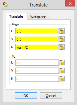
Note: This translation will move the structure down so that it is symmetrical around the XY plane.
The model has magnetic symmetry across the XZ plane and electric symmetry across the XY plane. The computational resources can be reduced by allowing the solution kernel to utilise symmetry. Note that this step is optional and you are encouraged to remove symmetry later to compare the differences in resources.
-
On the 3D View
context tab, on the Display options tab, in the
Solver display group, click the
 Symmetry icon.
-
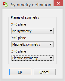
Specify the following symmetry:
- Y=0 plane: Magnetic symmetry
- Z=0 plane: Electric symmetry
Optional: Hide the symmetry.
-
On the 3D View
contextual tabs set, on the Display tab, in the
Method display group, click the Symmetry icon.