Adding Waveguide Ports
Add waveguide ports and ensure the ports have the correct orientation.
-
Add the first waveguide port on the face at the most positive X position using
one of the following workflows:
- In the 3D view, repeatedly left-click until the required face is highlighted.
- Open the right-click context menu of the face and select .
Tip: All sources are also accessible from the ribbon on the Source/Load tab.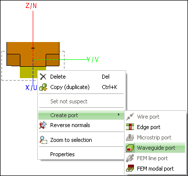
-
Use the default settings for the port.
Note: Ports are simply connection points or place holders on the geometry where sources can be added. Waveguide ports that do not have sources are considered to be absorbing waveguide terminations.
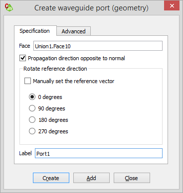
While the Create waveguide port (geometry) dialog is open, a preview of the waveguide port is displayed in green in the 3D view. Note that the reference vector is a silver line on the port face from the centre towards the positive Z direction.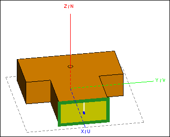
- Click Add to add the waveguide port, but do not close the dialog.
-
Add the third waveguide port at the face at the most positive Y position.
- Select the face in the same manner as for the first port.
- Use the default port label, Port3.
- Click 180 degrees to ensure the correct reference direction.
- Click Create to add the port and to close the dialog.
If all the steps have been followed correctly, the structure should look similar to the image. Note the port locations.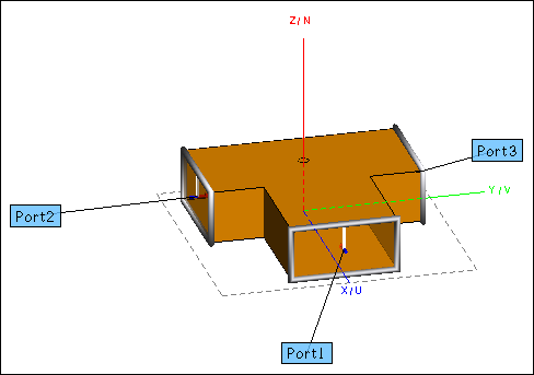
Tip: It may be necessary to enable the port annotations. On the 3D View context tab, on the Display options tab, in the Entity display group, click the Port annotations icon.