LTE Urban
Perform network planning for an urban scenario using long-term evolution (LTE).
Sites and Antennas
The model has six sites where each site consists of three antennas placed at a height of 35 m. The sites are placed at different locations throughout the urban area for the best coverage. Each antenna of the site has a directional radiation pattern intended to cover a sector of 120 degrees. The different frequencies used for propagation are around 2.6 GHz, and the transmitter power per antenna is 46 dBm.
Air Interface
Computational Method
For an urban environment, the dominant path model (DPM) is well-suited. DPM focuses on the most relevant path, which leads to shorter computation times compared to 3D ray tracing.
Results
Propagation results show at every location the power received from each transmitting antenna. Figure 1 shows the received power from Site 1 Antenna 1 at a height of 1.5 m
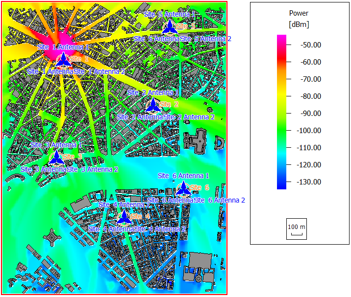
Figure 1. Power of Site 1, Antenna 1.
- cell area
- site area
- best server
- maximum data rate
- minimum required transmitter power
- maximum received power
- SNIR
- deception probability
- number of streams
- throughput for all modulation and coding schemes
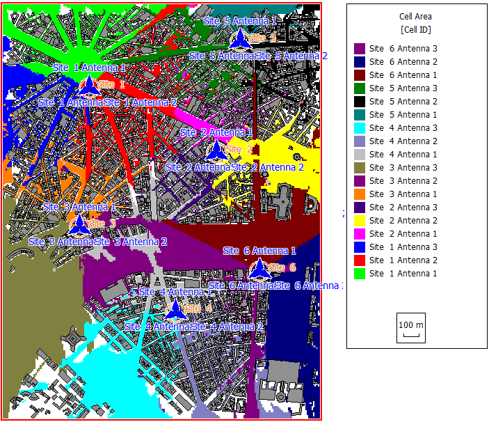
Figure 2. Cell area results for the network planning.