Indoor LTE with Components
Perform network planning for long term evolution (LTE) in an indoor scenario of a two-story building.
Model Type
This is an example of an indoor network planning project based on a description file for an air interface. The model consists of a two-story building with a large indoor area.
Using Component Databases
ProMan can model complex radio networks in indoor environments using predefined components from a component database. The component approach is advantageous in that various parameters of the devices (for example, such as the model, type, and price) can be stored in combination with the technical details such as losses and supported frequency bands.
If a component is modified, all components in projects that are linked (in the component properties) to this component catalogue are also adjusted automatically. A separate component manager application, CompoMan is used to store and edit the components in the component catalog1.
Components
This project contains components for the installation of the network infrastructure. If components are used, it is not possible to define individual prediction areas for each cell/transmitter. Therefore the prediction area is identical for all transmitters.
Air Interface
A list of different modulation and coding schemes are found on the Air Interface tab, under Transmission Modes (MCS). Overhead and interference associated with having two MIMO streams on the same carrier are specified here.
Computational Method
Results
Propagation results show at every location the power received from each transmitting antenna. Results are available for prediction planes at heights of 1.5 m and 5.5 m.
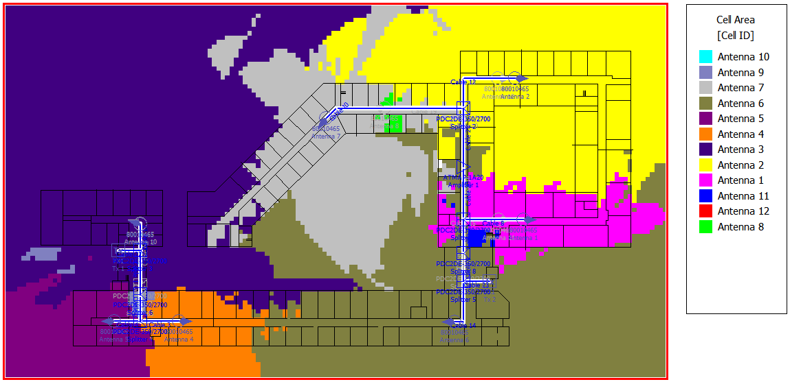
Figure 1. Network results for the two-story building - cell area. The cell area shows the different zones for antennas used in the model.
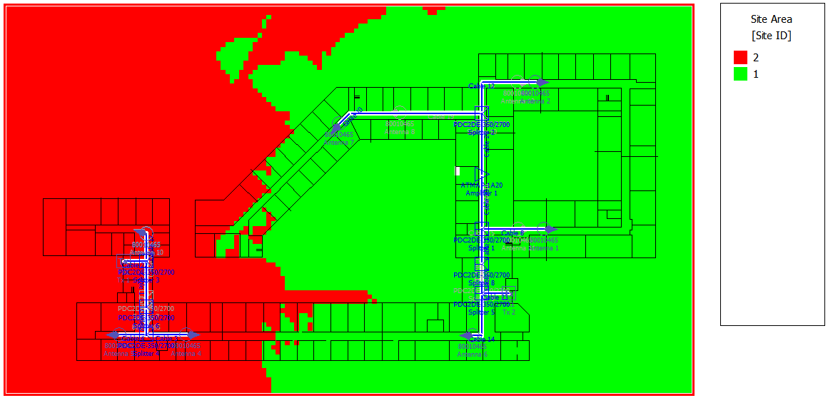
Figure 2. Network results for the two-story building - site area. The site areas for transmitters Tx1 and Tx2 are displayed using two different colors, site 1 in green and site 2 in red.
The type of network simulation is a static simulation (homogeneous traffic per cell). The network simulation calculates, for example, the maximum data rate and the maximum throughput for both downlink and uplink. Various network results for the defined modulation schemes can be viewed by selecting Results: Network in the result tree.
The maximum data rate in downlink is displayed in Figure 3.
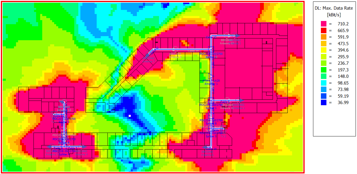
Figure 3. The maximum data rate for the two-story building.