Perform network planning using code division multiple access (CDMA) EVDO inside a
single-story building.
Sites and Antennas
Three antennas are placed at different locations for the best indoor coverage. Two
antennas operate at 2110.62 MHz, and the third operates at 2115.62 MHz. All antennas
are omnidirectional and mounted at a height of 2.5 m. All antennas transmit
individual signals.
Tip: Click Project > Edit Project Parameter and click the Sites tab to view the sites
and antennas.
The two antennas on the same carrier cause interference.
Air Interface
The air interface is defined by a CDMA wireless standard (.wst)
file. CDMA/WCDMA/HSPA (code division multiple access) is selected for multiple
access.
Tip: Click Project > Edit Project Parameter and click the Air Interface tab.
The duplex separation of 190 MHz between downlink (DL) and uplink (UL) is
accomplished using the frequency division duplex method.
Computational Method
As the model is a large building, the computation method used for such models is the
dominant path model (DPM). The DPM method focuses on the most
relevant path, which leads to shorter computation times compared to the standard ray tracing model (SRT).
Tip: Click Project > Edit Project Parameter and click the Computation tab to change
the model.
Results
Propagation results show the power received from each transmitting antenna at every
location.
To increase the data rate without increasing bandwidth and power, different
modulation techniques are used (16-QAM). An increase in the data rate increases the
bit error rate. The data rate, Data 2.4M, is too high data
for communication to take place at all. Therefore no results are shown even close to
the transmitter. It is observed that when the value for the defined threshold
Eb/N0 is reduced, communication at this fastest rate is
possible.
Tip: On the Air Interface tab, in the
Transmission Modes (MCS) group, click the
Edit button. On the Transmission
Mode dialog, change the value for Eb/No (min.
required).
The type of network simulation is a static simulation (homogeneous traffic per cell).
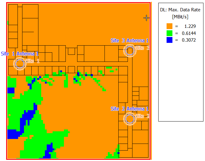
Antenna 1 and antenna 2 operate on the same carrier frequency. Since these antennas
transmit individual signals, they do not form a distributed antenna system in this
case, but they can interfere with each other. This is visible in the results - the
maximum data rates in locations between these two antennas are notably lower.
Figure 1. Upload maximum data rate - the data rate is lower, where antennas 1 and 2
interfere.