LTE Indoor
Perform indoor network planning for long term evolution (LTE).
Model Type
This is an example of an indoor network-planning project based on a description file for an air interface (a .wst file). The model is a single-story office building.
Sites and Antennas
There are three antennas at different locations for the best coverage. All antennas have an omnidirectional radiation pattern and transmit at carrier frequencies near 2.1 GHz. Two different carrier frequencies are used by the three antennas, which means that two antennas use the same carrier.
Air Interface
Computational Method
Empirical losses are used for the computation of the signal level along the propagation path. Empirical material properties are often easier to obtain than electrical properties.
Results
Propagation results show, at every location, the power received from each transmitting antenna individually. Figure 1 shows a prediction at 1.5 m.
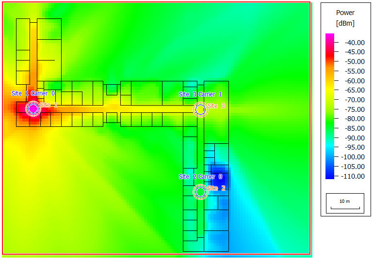
Figure 1. Propagation results: Power of site 1.
- cell area
- site area
- best server
- maximum data rate
- minimum required transmitter power
- maximum received power
- SNIR
- deception probability
- maximum number of parallel streams at pixel
- throughput at pixel in transmission mode
- Line-of-sight (LOS) condition: a direct line of sight between transmitter and receiver.
- Obstructed-line-of-sight (OLOS) condition: transmitter and receiver can be connected without a wall intersection - the transmitter and the receiver are in the same corridor but without having a direct line of sight (only in indoor scenarios).
- Non-line-of-sight (NLOS) condition: No direct line of sight between transmitter and receiver - the transmitter cannot see the receiver and vice versa, due to shadowing by obstacle(s).
- Line-of-sight for buildings but shadowing caused by vegetation objects (LOS-V).
- Non-line-of-sight for buildings and shadowing caused by vegetation objects (NLOS-V).
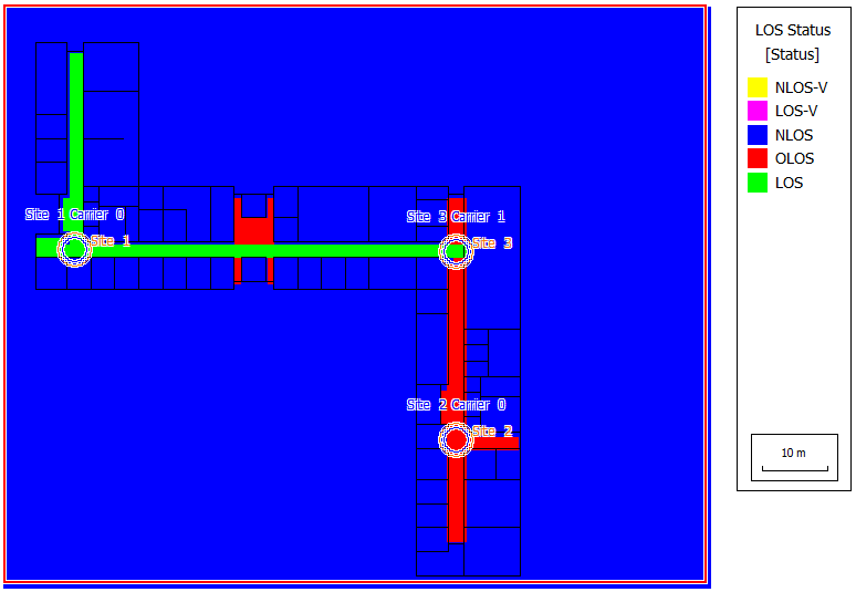
Figure 2. Line-of-sight (LOS) results for site 1.
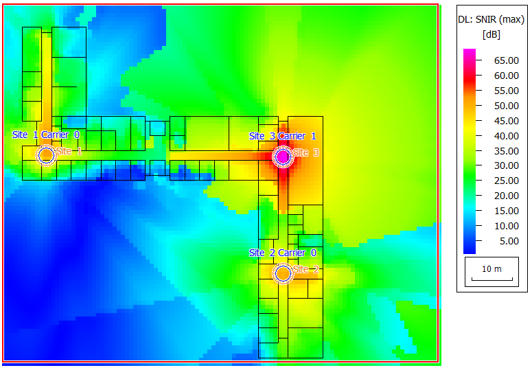
Figure 3. SNIR results for the downlink - the SNIR is low outside the building between sites 1 and 2, leading to low data rates.