Tutorial: Line-Arcs and Circles
Sketch a complex shape using line-arcs and circles.
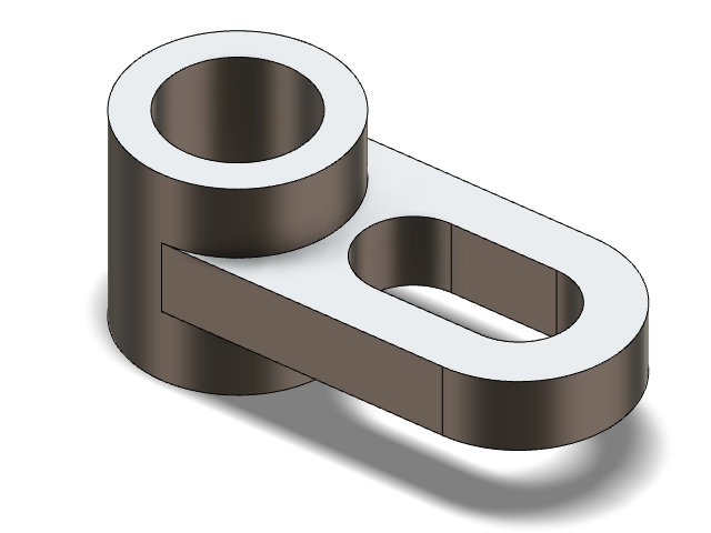
In this lesson, you will learn how to:
- Sketch line-arcs and circles
- Trim a sketch to create a slot
- Use the Extrude and Trim tools to finish the sketch
Create a Circle Sketch
-
Start Inspire Studio. Or if it is already open, click the
New model tool on the File
icon.

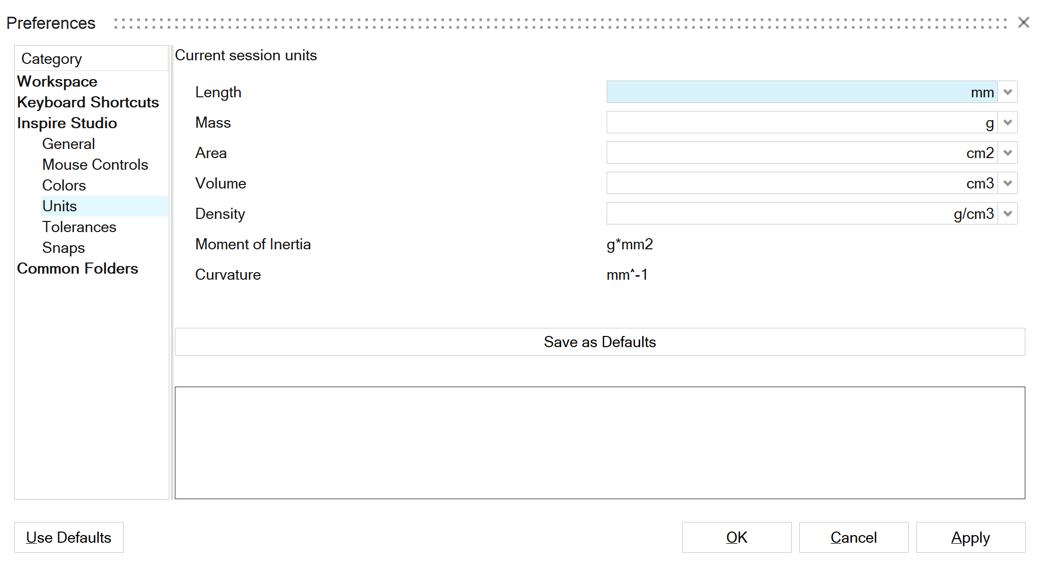
- On the File menu, click the Preferences button.
- Under units, select mm for length.
- Under Inspire Studio > Units, for Length, select mm.
-
Click the Save as Defaults button. Click
Apply, then OK to close.
- On the ribbon, click the Sketching tab.
-
In the Circles tool group, click the
Circle icon.

-
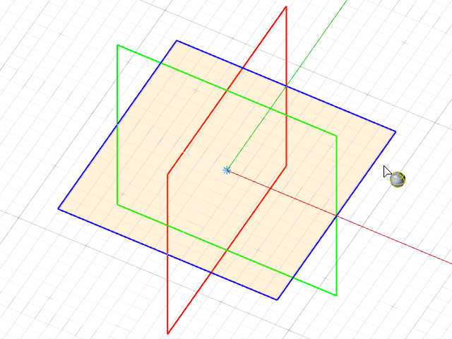
Click the Top sketch plane.
The view automatically aligns orthographically.
-
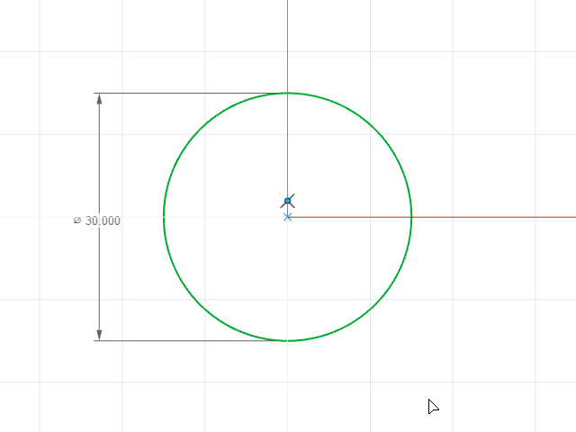
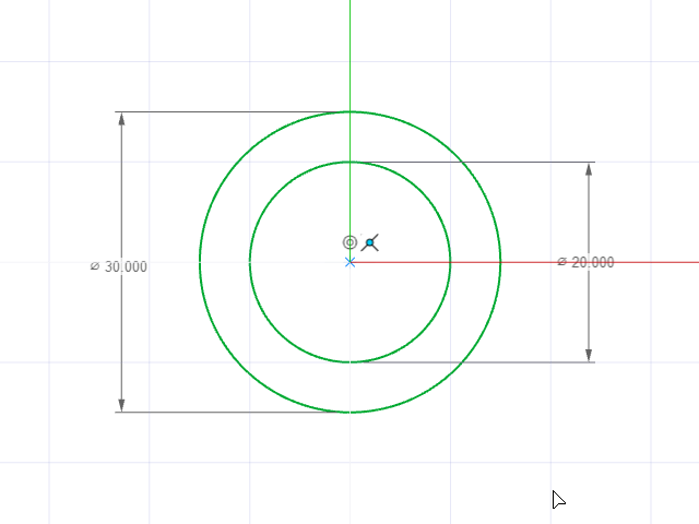
Draw a circle by snapping the center to the global origin point. Dimension the
circle 30 mm.
-
Draw a second circle; make it concentric with a diameter of 20
mm.
- Right-click and mouse through the check mark to exit, or double-right-click.
- Save the file as Level1_Tutorial2.
Extrude the Circle Sketch
- On the ribbon, select the Surfaces tab.
-
Open the Extrude tool:
- On the Surfaces tab, click the Extrude icon.
- While holding down Alt, right-click to open the tool belt, and then click the Extrude icon.

-
Modify the sketch curve:
-
Click the sketch curve in the modeling window.
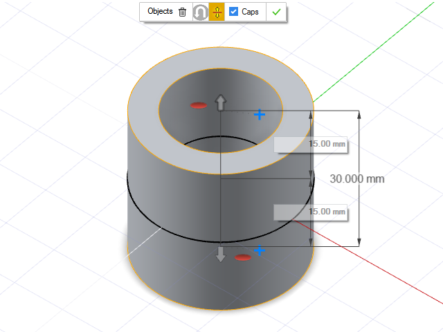
By default, the sketch curve is extruded according to the sketch dimensions.
- Change the extrusion value to 15 mm.
- In the guide bar, turn on Symmetric Distance.
- In the guide bar, select Caps.
-
Click the sketch curve in the modeling window.
- Save the model.
- Right-click and mouse through the check mark to exit, or double-right-click.
Create a Line-Arc Sketch, Fillet, and Extrude
- Before drawing the line-arc sketch, hide the circle sketch by clicking on its icon on the World tab in the Model Browser.
- On the ribbon, click the Sketching tab.
-
Click the Import Entities icon.

-
Click the Top sketch plane.
The view automatically aligns orthographically.
-
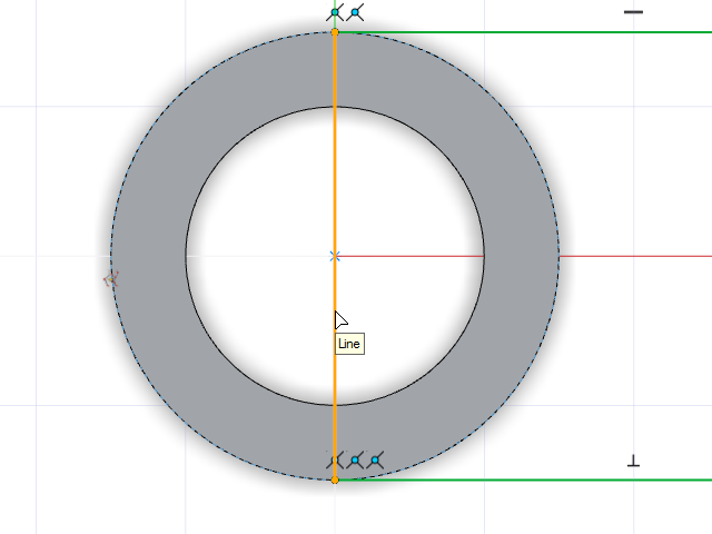
Select the top outer edge of the extrude as shown. An entity will be imported
into the current sketch. Complete the sketch using the Line tool.
- Double click the line-arc sketch to edit.
-
On the Sketching tab, click the
Fillet icon.

-
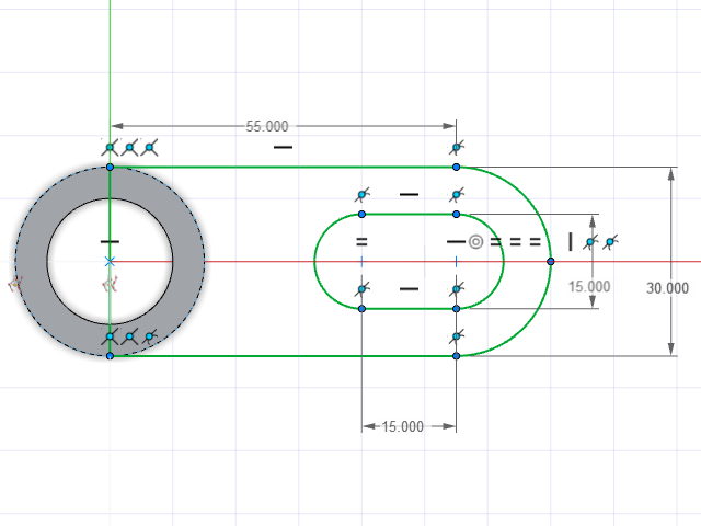
Add a fillet of 15 mm on the top and bottom right
vertices as shown.
-
Draw a slot using the Line tool.
Note: To turn on/off arc mode, press Shift.
- Right-click and mouse through the check mark to exit, or double-right-click.
-
Dimension the sketch as shown.
- On the ribbon, select the Surfaces tab.
-
Click on the Extrude icon.

-
Change the extrusion value to 5 mm, turn on
Symmetric Distance, and add
Caps.
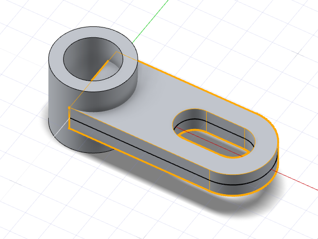
- Right-click and mouse through the check mark to exit, or double-right-click.
Extract and Trim an Edge
- On the ribbon, click the Curves tab.
-
Click the Edge Extract icon.

-
Select the inner edge of the cylinder as shown.
- On the ribbon, click the Modify tab.
-
Click on the Trim icon.

-
Using the Trim tool, select both the Edge Extract from
the previous step and the two solid bodies in the view. Turn on the
Keep Exterior option to obtain the best result.
- Right-click and mouse through the check mark to exit, or double-right-click.