MV-7031: Tracked Vehicle Modeling
In this tutorial, you will learn how to use MotionView to build a tracked vehicle and MotionSolve to simulate the vehicle passing over a slope.
Open and Review the Model
From
the mbd_modeling\interactive\track folder, copy the files
Track_Start.mdl and soil_input.dat to your
<working directory>.
-
Click the
 (Open Model) icon to open the
Track_Start.mdl model file.
(Open Model) icon to open the
Track_Start.mdl model file.
-
Review the model.
- The model is in the mm, Kg, N, sec unit system.
- The model has two systems: Body and Suspension.
- The Body system contains the Vehicle body (Frame) and Engine fixed to each other.
- The Suspension system has three trailing arms connected with a torsional spring damper.
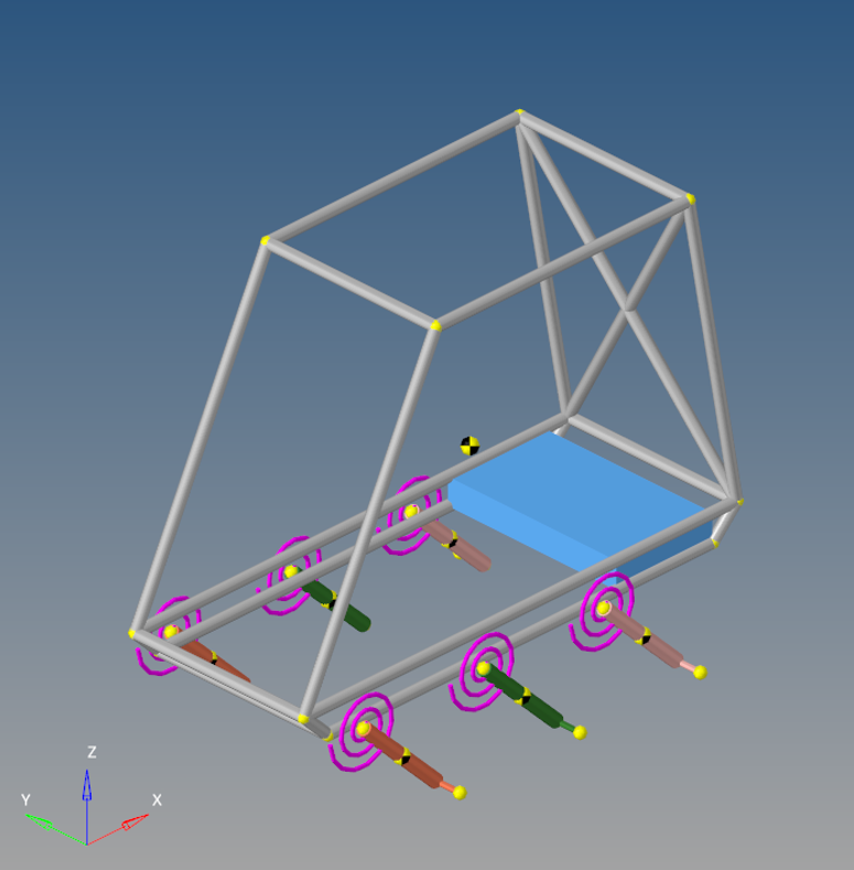
Figure 1.
Create Rolling Systems
-
From the Model menu, select .
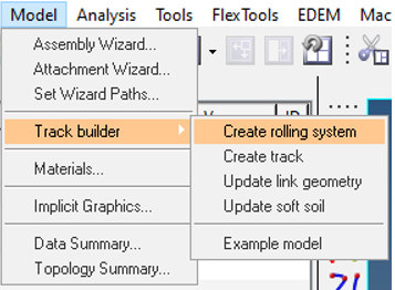
Figure 2. -
Use the table below to create a Sprocket type rolling system.
Rolling System Varname Rolling System Label X Y Z Radius Thickness Number of Teeth Attach to Single/Left Attach to Right Sysr_spr Sprocket 0 -500 400 200 100 16 Frame Frame 
Figure 3. -
Use the table below to create multiple Wheel type rolling systems.
Tip: Use the Apply button to keep the dialog open when creating multiple rolling systems.
Rolling System Varname Rolling System Label X Y Z Radius Thickness Attach to Single/Left Attach to Right Sysr_frntw FrontWhl 300 -500 0 200 100 Front Arm-Left Front Arm-Right Sysr_midw MidWhl 800 -500 0 200 100 Mid Arm-Left Mid Arm-Right Sysr_rearw RearWhl 1300 -500 0 200 100 Rear Arm-Left Rear Arm-Right 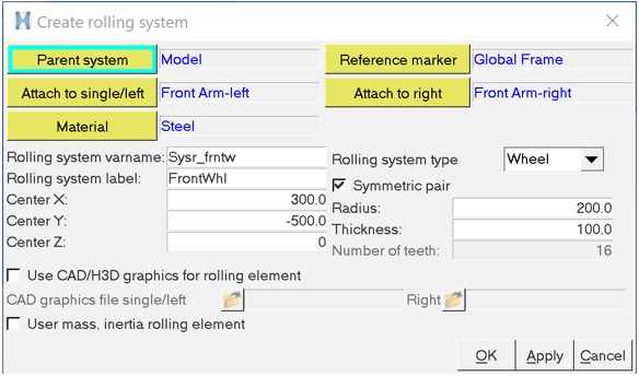
Figure 4. -
The model with all of the defined rolling systems is shown below:
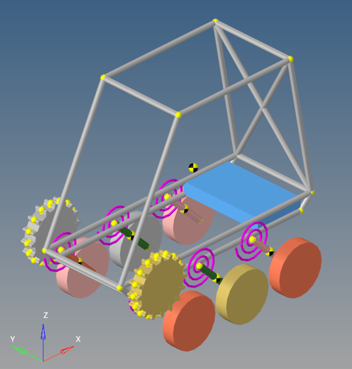
Figure 5.
Create Track Systems
-
From the Model menu, select .
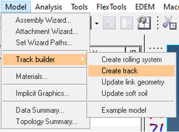
Figure 6. -
Click Apply to create the track for the left side.
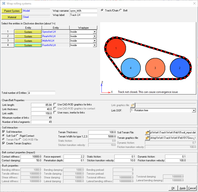
Figure 7.The Track with Terrain Graphics is shown below: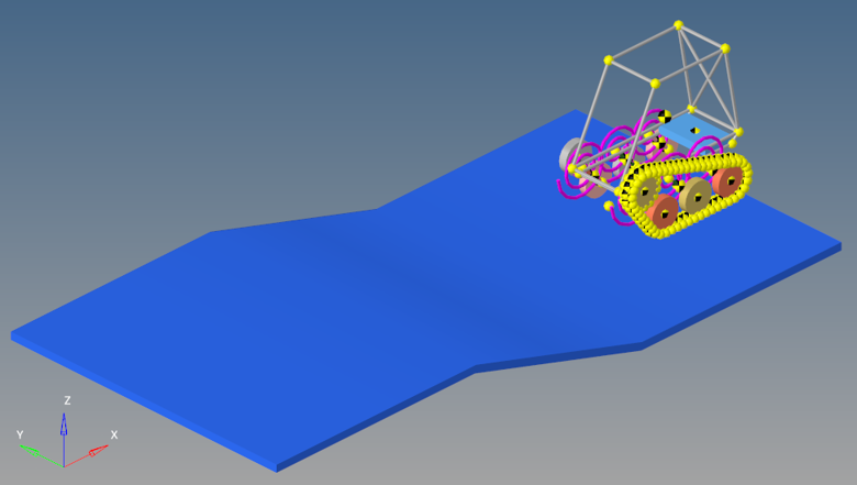
Figure 8. -
The completed model is shown below.
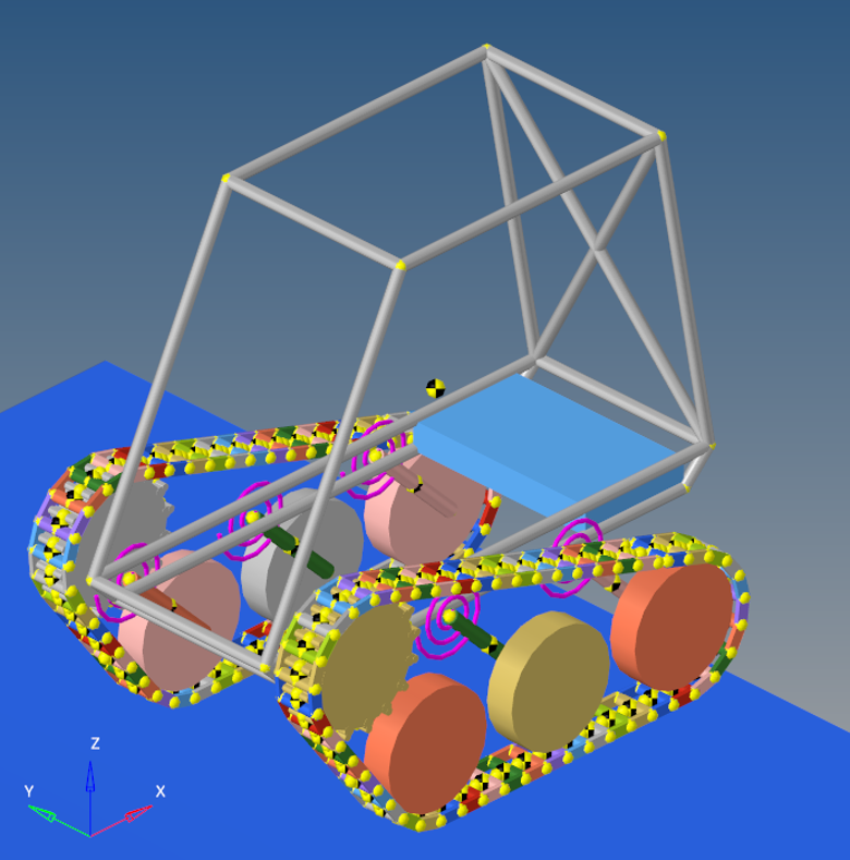
Figure 9.
Verify Soil Properties
-
From the Model menu, select to view the parameters.
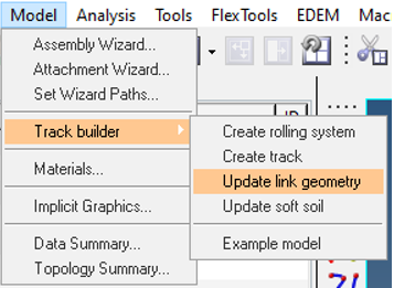
Figure 10. -
The Update Link Geometry dialog contains some basic properties and link
geometric properties. Review the data and click Cancel to
close the dialog.
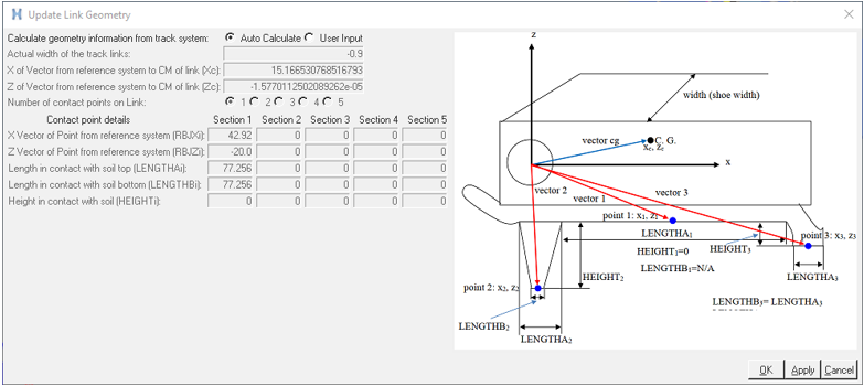
Figure 11. -
From the Model menu, select to view the parameters.
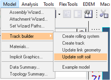
Figure 12. -
The Update soft soil properties dialog contains the
details of terrain and soil properties. Review the data and click
Cancel to close the dialog.
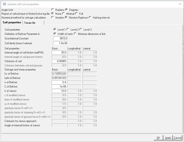
Figure 13.Note: To learn more about the link and soft soil properties, please see Track Model.
Simulation and Post-Processing
-
Click the Animate button to load your results in a
 HyperView window.
-
From the Animation toolbar, click the
 (Start/Pause Animation) button to animate the
model.
(Start/Pause Animation) button to animate the
model.
-
Visualize the animation.
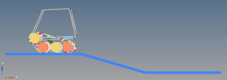
Figure 14. -
From the Page Controls toolbar, click the
 (Add Page) icon.
-
In the Select Application drop-down menu, change the client to
 HyperGraph 2D.
-
From the Build Plots panel, click
 to load
the .abf file from the MotionSolve run.
to load
the .abf file from the MotionSolve run.
-
Plot the Sinkage of link 0 under Y type -
REQSUB.
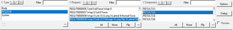
Figure 15.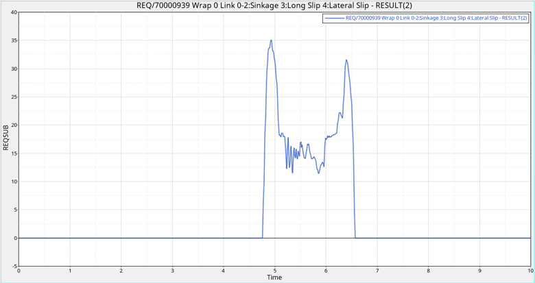
Figure 16.