MV-7011: Co-Simulation with Activate via Function Mockup Interface (FMI)
In this tutorial, you will learn about the process of setting up an MBS model to co-simulate with Activate by following the FMI.
The co-simulation “flavor” of the FMI prescribes a protocol for different software to iteratively communicate data with one another, thus enabling multiple solvers to co-simulate amongst one another.
By leveraging this interface, MotionSolve can co-simulate with Activate, or with any other software that supports the FMI standard. To do this, the MotionSolve model is first converted to a Functional Mockup Unit (FMU) which is a stand-alone modeling unit that represents the MotionSolve model. FMUs adhere to the protocol prescribed by the FMI and can thus be imported or exported by software that support this interface.
MotionSolve can export an FMU of type “co-simulation” which can be imported into other software such as 1-D simulators. The type “co-simulation” implies that the MotionSolve FMU is responsible for calculating its part of the solution i.e. MotionSolve is invoked at the time co-simulation is started.
This tutorial will describe the steps required to:
- Open and inspect the MBS model
- Export an FMU from MotionView
- Use the FMU to run a co-simulation analysis using Activate
- Review co-simulation results in Activate
A model representing a quad-rotorcraft is used for this tutorial. The model structure, rotor blades etc. are modeled using MotionView/MotionSolve and Activate is used to control the spin rate of the rotors to control the thrust and lateral movement of the rotor. Roll forces are applied to the rotorcraft to mimic the effect of wind. The aim of the simulation is to control the thrust to make the rotor achieve a target height.
Software required to complete this tutorial successfully:
- HyperWorks 2017.1 or later
- sT/Activate 2017.1 or later
Review the Model
-
From the Model-Main toolbar, click the Open Model icon
 .
Tip: You an also select .
.
Tip: You an also select . -
Review the model.
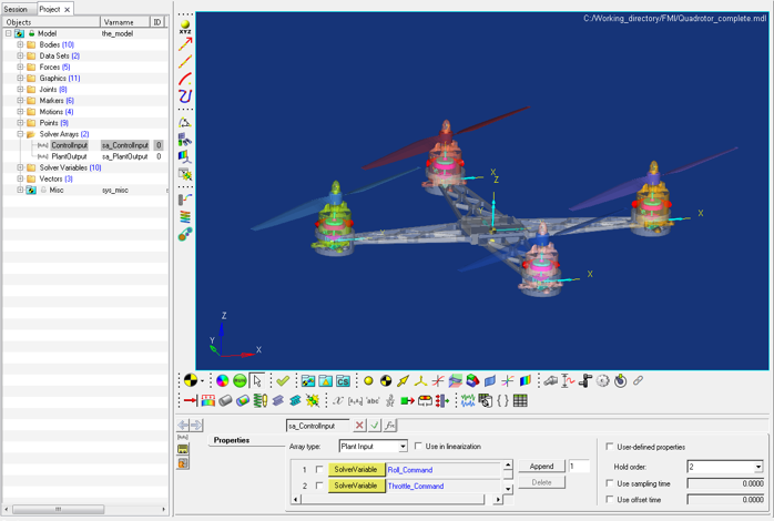
Figure 1.Note: The model has been instrumented to contain inputs (ControlInput) and outputs (PlantOutput). Outputs are signals sent by MotionSolve to the environment (Activate). Inputs are signals accepted by MotionSolve from the environment.In this example, the following outputs are computed by MotionSolve and passed to the external solver (Activate):Name Description Roll Angle The roll angle of the rotor craft in the global frame. Altitude The height of the rotor craft in the global frame. Pitch Angle The pitch angle of the rotor craft in the global frame. PosX The X coordinate of the rotor craft in the global frame. PosY The Y coordinate of the rotor craft in the global frame. VX The X velocity of the rotor craft in the global frame. VY The X velocity of the rotor craft in the global frame. The following inputs are expected from the external solver by MotionSolve:Name Description Roll_Command The control signal for controlling the roll of rotor craft. Throttle_Command The control signal for controlling the throttle of rotor craft. Pitch_Command The control signal for controlling the pitch of rotor craft.
Export MDL as an FMU
-
From the Standard toolbar, click the Export Model icon
 .
Tip: You an also select .The Export Model dialog is displayed.
.
Tip: You an also select .The Export Model dialog is displayed. -
Select the Export as Functional Mockup Unit (FMU) option
and use the Select FMU file browser
 to designate the file name for the FMU as
Quadrotor.fmu.
to designate the file name for the FMU as
Quadrotor.fmu.
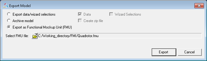
Figure 2.
Import the FMU in Activate
-
Launch Activate and open the
Quadrotor_Control_fmu.scm file from your <working
directory> using the Open Model button
 .
Tip: You an also use the menu option to select the Quadrotor_Control_fmu.scm file.
.
Tip: You an also use the menu option to select the Quadrotor_Control_fmu.scm file.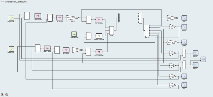
Figure 3. -
From the Palette Browser on the right, double-click Activate >
CoSimulation and drag-drop the FMU block
into the model GUI.
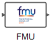
Figure 4.Note: If the Palette Browser is not visible on the right, you can turn it ON by clicking in the Menu. -
Double-click on the FMU block to specify the FMU.
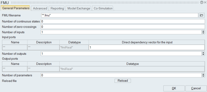
Figure 5. -
Click the browse file button
 and select the FMU exported from MotionView.
Note: Once the FMU is loaded, you will notice that several of the other fields in this dialog are auto-populated.
and select the FMU exported from MotionView.
Note: Once the FMU is loaded, you will notice that several of the other fields in this dialog are auto-populated.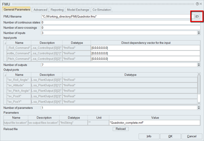
Figure 6.Tip: You can specify the different location of the output files from MotionSolve (.mrf, .abf, .h3d, etc.) by changing the text in the parameter with the name “Output file location”. -
Click OK to select the FMU and exit.
The FMU block is changed to reflect the right number of inputs and outputs based on the FMU.
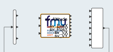
Figure 7.Tip: You can resize the FMU block until the input and output names become visible.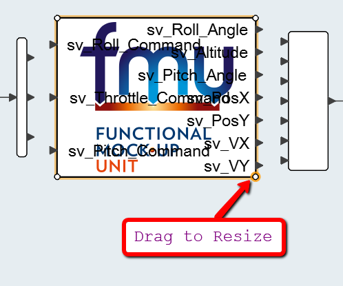
Figure 8. -
Connect the FMU block to the rest of the model through connector ports.
After connection, your model should look like the one shown below.
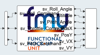
Figure 9.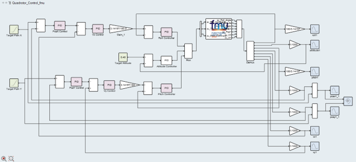
Figure 10.
Run the Activate Model
-
Using the option, set the MotionSolve license
to the location of the MotionSolve license modules.
For example, D:/Program
Files/Altair/2017.1/hwsolvers/common/bin/win64.
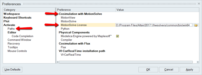
Figure 11. -
Click the Run the Simulation button
 to begin the co-simulation.
Note: Activate invokes the FMU which in turn generates an XML from the packaged MDL and uses that to begin the co-simulation. The co-simulation is based on inter-process communication (IPC), thus MotionSolve is started on a new thread.
to begin the co-simulation.
Note: Activate invokes the FMU which in turn generates an XML from the packaged MDL and uses that to begin the co-simulation. The co-simulation is based on inter-process communication (IPC), thus MotionSolve is started on a new thread.
Review the Results
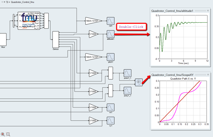
Figure 12.
The altittude1 scope shows the altitude of the rotor craft. After about 8 seconds, the quadrotor seems to stabilize at the desired height.
The ScopeXY scope shows the target X, Y path (red) vs. the actual X, Y path (pink) of the quadrotor.
You can retrieve results from the MotionSolve output files like the MRF, ABF, PLT, H3D etc. You may also create expressions in your MotionSolve model that are used solely to monitor the system.