ACU-T: 7100 DOE Study of an HVAC Duct
Prerequisites
To run this simulation, you will need access to a licensed version of HyperWorks CFD, HyperStudy, and Inspire Studio.
Prior to running through this tutorial, copy HyperWorksCFD_tutorial_inputs.zip from <Altair_installation_directory>\hwcfdsolvers\acusolve\win64\model_files\tutorials\AcuSolve to a local directory. Extract the following files from HyperWorksCFD_tutorial_inputs.zip.
- HVAC_Duct.istudio
- HVAC_DUCT.hmtpl
- HVAC_DUCT.tcl
- acuRun_HST.bat
Problem Description
The outline for this tutorial is shown in the figure below.
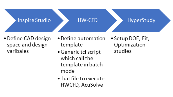
Figure 1.
You will be looking at a DOE study of an HVAC duct containing 10 parameters with values ranging from 0 to 100. You will be interacting with three of Altair’s products, namely Inspire Studio, HyperWorks CFD, and HyperStudy. The following list of files need to be present in your working directory before proceeding with the design study:
- HVAC_Duct. hmtpl
- Contains the template which will be used to execute the boundary conditions, mesh, and solver commands in HyperWorks CFD.
- HVAC_Duct. ist2hst
- Contains the parameter list along with the range of values for which the design study must be carried out.
- HVAC_Duct. tcl
- Contains the script to execute HyperWorks CFD. This is a generic tcl and you only need to edit the script to define the global mesh size in line 18 of provided the tcl file.
- acuRun_Hst.bat
- Contains the execution lines for the above files, AcuSolve solver, and output generation. This file is problem dependent and you have to change AcuSolve/AcuTrans arguments according to the given problem.
- The executable (.exe), batch(.bat), and problem directory paths present in the acuRun_Hst.bat need to be updated with their respective locations on your machine. This can be carried out using any text editor (for example, Notepad).
- For this process, the .hmtpl, .ist2hst, .tcl, and .iStudio files must have same name.
You will start this tutorial with a pre-setup of the HVAC model in a studio file with a set of 10 parameters and the template file to execute the various steps in HyperWorks CFD.
Generate the Design Variable File Using Inspire Studio
-
From the Home tools, Files tool group, click the Open Model tool.

Figure 2. -
Click the Design Table tool.

Figure 3.A Design Table dialog opens containing a list of pre-assigned parameters for the HVAC model.
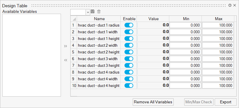
Figure 4.
Generate the HVAC Parasolid Model
- From the menu bar, click .
- Select Parasolid from the file types drop-down list.
- Name the file HVAC_Duct then click Save.
- Close Inspire Studio.
Define the Template File in HyperWorks CFD
-
Click the arrow next to the Home tool set, then
select Template Manager.
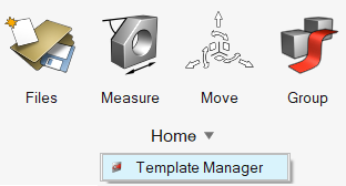
Figure 5. -
Click
 in the Template Manager dialog and select an
existing template, in this case HVAC_Duct.hmtpl.
in the Template Manager dialog and select an
existing template, in this case HVAC_Duct.hmtpl.
-
Click Open to load the template file.
The template is populated as shown in Figure 6. Any modifications to the template can be carried out here.
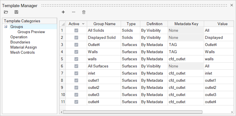
Figure 6. -
Click
 to save and export the template file.
Overwrite the existing file with the newly modified template file.
to save and export the template file.
Overwrite the existing file with the newly modified template file.
Open HyperStudy and Create a Project
-
Click the New tool.

Figure 7.
Add the Inspire Studio Model
-
Under the Define models tab, select Add Model.
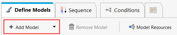
Figure 8.
Set Up the Model File
-
Click
 in the Resource column.
-
Rename the default HVAC_Duct.stl file type to
HVAC_Duct.x_t in the Solver Input File column.
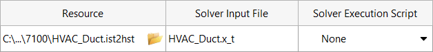
Figure 9. -
Click OK.

Figure 10. -
Click in the Path field of the newly
created script.
-
Click Next.
Define Input Variables is now displayed with the list of variables populated in the Bounds tab.
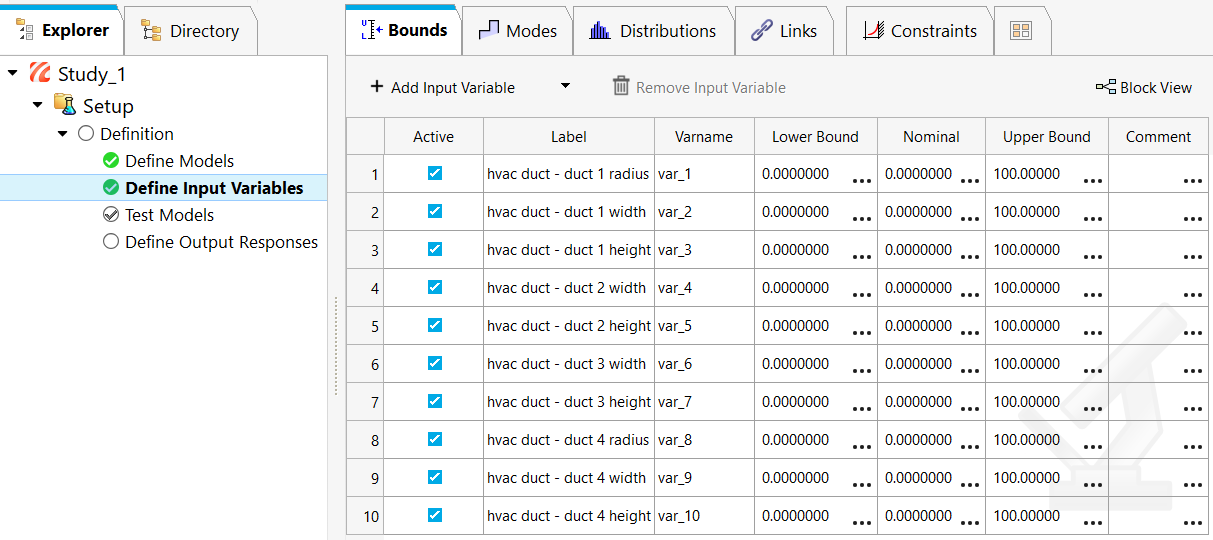
Figure 11.
Execute Test Models
-
Click Write under the Test column.
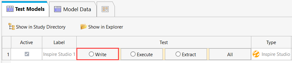
Figure 12.A green check mark appears next to the Write command to indicate that the operation has been successfully executed. -
Click
 in the Expression column.
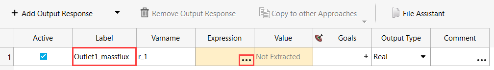
Figure 13. -
Click in the File column.
-
In the Data Source Builder dialog, click to load the outlet flux values of the first port.
-
Search for the Outlet1_MassFlux.osi file in the m_1 folder
and click Open.
Observe a preview of the dataset as shown in the Figure 14 to ensure that the file was loaded properly.
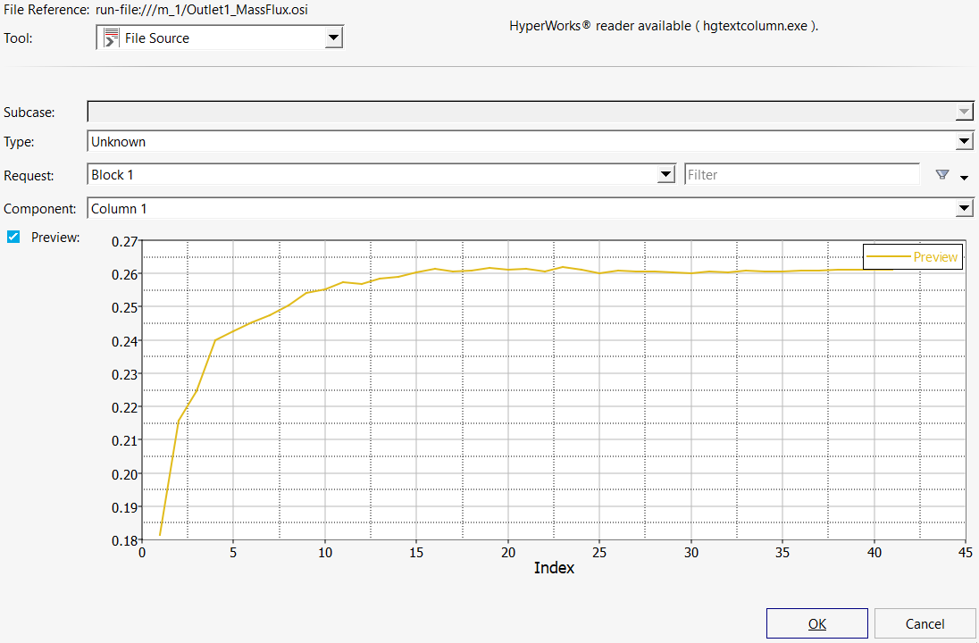
Figure 14. -
Click the arrow next to the Insert Varname button and
select Last Element from the drop-down.
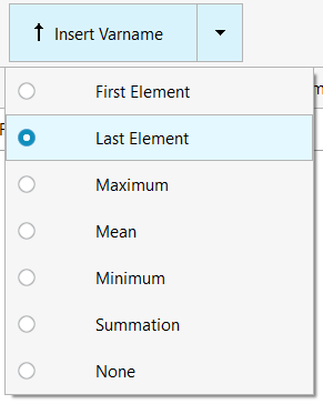
Figure 15. -
Follow steps 4-14 to generate output responses for outlets 2, 3, and 4.
Your dialog box should look like the one in Figure 16 after this step.
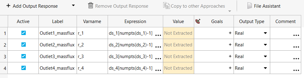
Figure 16. -
Select Test Models from the Setup drop-down.
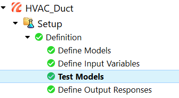
Figure 17. -
Click Extract.
A green check mark appears next to the Extract command to indicate that the operation has been successfully executed.The Value column in the Define Output Responses tab is now populated with the Last iteration value of the dataset.
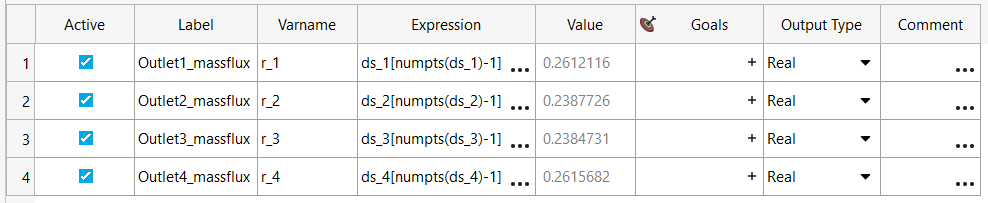
Figure 18.The HyperStudy file is now set up to carry out the Design of Experiments run. The Design study can be initiated adding it as a part of the Study file.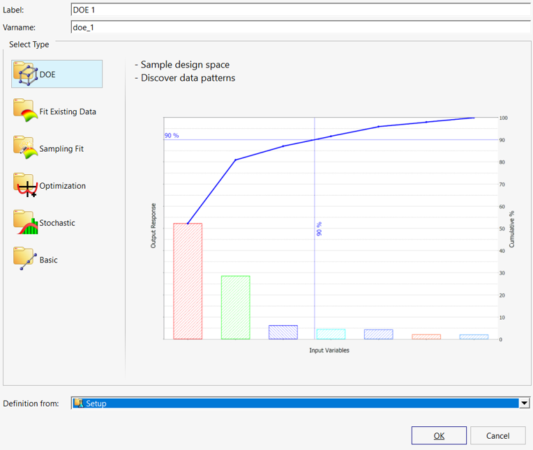
Figure 19.