Update 1D Element Properties Using Cross Sections
Use the Section Property tool to update properties assigned to bar2 or rod elements (target) using a cross section on various entities as the source.
- A collection of solid geometries
- A collection of surfaces
- A collection of elements (2D & 3D)
-
From the Mesh ribbon, click the Section
Property tool.

Figure 1. -
Use the microdialog options to define plane locations
and where intersections are generated on source elements.
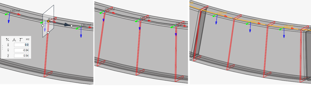
Figure 2. Section Cut: a) Single cut b)Per element c)Per node- Single cut
-
Update a list of elements with a single property extracted from a single user-defined location. Click
 to define the cutting plane.
You can adjust the base point and plane normal. Placing the
cutting tool on a target element will adjust the plane’s
normal along the selected element’s X axis.
to define the cutting plane.
You can adjust the base point and plane normal. Placing the
cutting tool on a target element will adjust the plane’s
normal along the selected element’s X axis.A single preview shows intersections before proceeding. Changing the source updates the preview.
The reference point (see Orientation and Offset) is the intersection of the cutting plane with a target element. This defines the reference orientation and offset.
If you perform a section cut using a plane which does not intersect any of the target elements (Figure 3), then the reference point is extracted from the plane's base point.
You need to pay attention to the local normal and relative position of the manipulator in the section cut to obtain accurate result to assign to its target selection. Target elements must have consistent orientation.
-
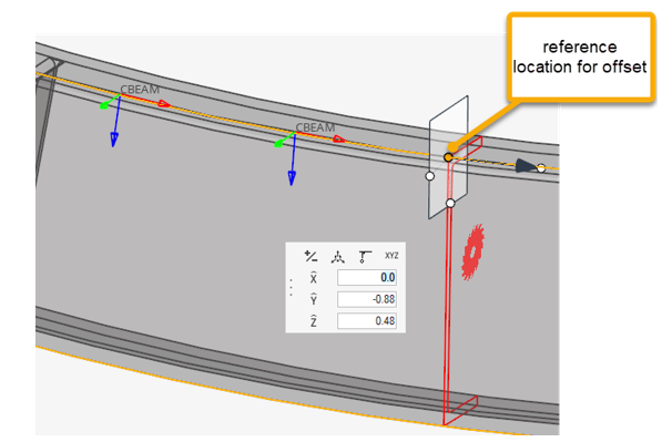
Figure 3. Single cut out of targets - Cut per element
- Automatically perform a section cut on each target element. As
explained in Orientation and Offset, the resultant section is valid per element no matter its
orientation. The intersection is done by default on the midpoint
of the target element. You can set a value (0 to 1) to specify
the parametric position between the target element’s nodes
(Figure 4). The orientation can’t be changed. The
plane is normal to the target’s X axis.
Since a cut is performed per element, all meshing processes and calculations are done as many times as target elements selected. This is obviously more time consuming than a single cut. Whenever a region of multiple targets share the same section, it is advisable to use the Single Cut method to reduce computation time.
-
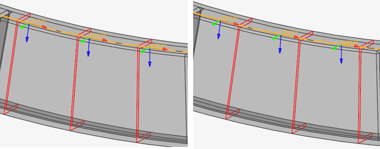
Figure 4. Intersection at 30% resp. 80% of each element - Cut per node
- A cut is performed on each node of the target elements. If adjacent elements form a vertex angle between their X axis below the threshold angle tolerance, a single cut is done for common nodes; otherwise, one cut per element is performed at the same node using different normal. No additional test is done on (Y,Z) axis deviation from adjacent elements. Properties will be created with two beam sections: one at each end station. If a single cut is done on a node, the two adjacent properties share the same beam section for their relative station.
-
Click
 in the microdialog to
toggle between a finite and infinite plane
in the microdialog to
toggle between a finite and infinite plane
In some situations, it is best to consider a finite plane to intersect sources. In the Figure 5, using the (default) infinite planes would result in undesired regions considered during trimming. In such cases, you can switch to a finite plane and define the width and height of the section cut. However, it is not possible to define the size location per location. The width and height will be common for all intersections.
Finite planes are available for all types of cuts (single | per element | per node) and all types of sources. However, when sources are Solid geometries, a cut is considered valid only if it fully crosses boundary surfaces (solid partial cut is not supported).
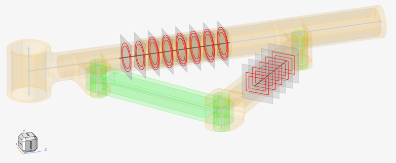
Figure 5. Finite size planes -
Click
 on the guide bar to define
how to handle welds and contacts.
See Disconnected Parts for more information.
on the guide bar to define
how to handle welds and contacts.
See Disconnected Parts for more information. -
Click
 .
.
The sectional properties calculation is launched. When the process is done, a review of the calculated sections is shown. Properties are created based on the element configuration and assigned to elements. Offset is applied to target elements. Material and beam sections are generated per property.
The review considers real section shapes (after inflates) as well as offsets. If you proceed with different selections or exit the tool, the graphic review goes away.
The actual shape of a section is currently not saved in the generic beam section generated. Using Beam details view will show an equivalent rectangle as usual.
Figure 6.
Sectional Property Evaluation Theory
The Section Property tool calculates the intersection between a plane and source entities. It can be a plane per 1D target element or a single cut at a user-defined reference location.
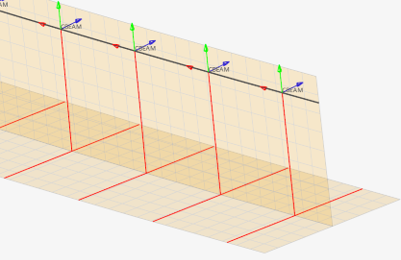 Figure 7. Intersections with shell with thickness |
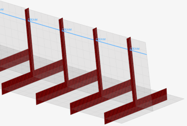 Figure 8. Mesh after section inflate |
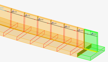 Figure 9. Intersections with solids (geometry) |
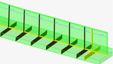 Figure 10. Mesh of solid intersections |
Material info is considered from each intersected entity. If source entities intersected are solids or surfaces, then the material is extracted from the component which holds the intersected geometry. If source entities are elements, then material info is gathered from each element (directly or through component).
Sectional properties are hence calculated following theory as described in: “Analysis and Design of Elastic Beams: Computational Methods, Walter D. Pilkey”
The material neutral axis is calculated along with stiffness terms EIyy, EIzz, GJ, and EA considering local material info. Shear Center and warping properties like torsional constant and warping constant are also calculated.
After sectional properties are calculated accounting for all materials, a regular homogeneous beam property is created referring to a single (homogenous) material and a generic beamsection.
You can specify a target material to be used for homogenization or let the tool auto-calculate the material property using effective young modulus. The beam section area and area moments of inertia are set based on the material's Young modulus to retrieve the same stiffness terms as calculated from the intersected entities.
In turn, if the material is auto-generated, its young modulus is derived from the section product EA and total area A as Eeff= (EA)sec/A. The area moments of inertia are then I=EI/ Eeff; Moments of inertias will deviate from geometric quantities in case of multiple materials, but the section’s Area is correct.
If a target material is provided, then its young modulus will be used; hence all geometric terms A, Iyy, Izz, Iyz may deviate from those calculated by closed form equations for similar geometric shapes.
Orientation and Offset
The elemental system of target 1D elements remain unchanged during the update process.
When a cross section is performed on a 1D element, its local X axis is taken as the section plane’s normal. The beamsection local 2D system (Y, Z) matches with the elemental axis (Y, Z). Sectional properties are hence valid in elemental system as defined. If orientation needs to be adjusted, it is advisable to update the element orientation first (see Orient Bar2 Elements).
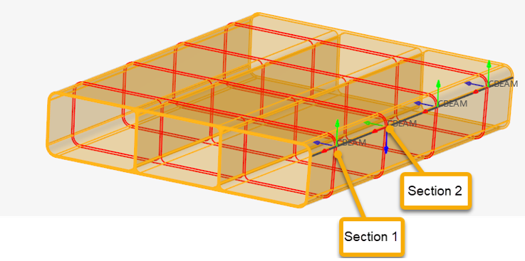
Figure 11. Section cut per element
Since a cut is performed per element in Figure 11, each section has its own local system matching the elemental system, as shown in Figure 12 & Figure 13. The origin of the system, from which Centroid and Shear Center coordinates are saved in the beamsection entity, is taken at the center of the bounding of the section in the local system.
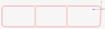
Figure 12. First section
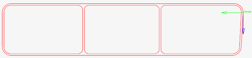
Figure 13. Second section
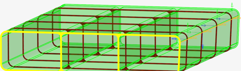
Figure 14. Calculated section after offset
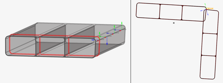
Figure 15. Single section cut on misaligned elements
Materials
If a region has no material assigned, the calculation uses E =1, nu =0, and G = 0.5 by default.
Otherwise, materials are extracted from properties (on elements or components). To account for material info on geometry, it is mandatory to assign a material to the component which holds the geometry. It is important to note that if a geometric component lacks material info, the engine will use defaults as mentioned before. It is fine if no other materials are in use, but might lead to inconsistent results if a mix of default and true materials are used in the same section.
Disconnected Parts
A section cut on a model may lead to disconnected regions. It could be because of separate bodies which are glued or welded, or because section undergoes a hole in model. A valid section needs to be connected to consider it as an equivalent beam section.
In any case, the Section Property tool generates a beamsection with geometric properties like area and second moments of inertia calculated. However, to fully complete the process and calculate shear center position as well as torsional & warping constants, the section need to be “connected”.
The tool provides two options called “weld” and “contact”.
- Welds
- The regions made of thin parts (intersections with 2D elements or surfaces) can be welded based on the line domain proximity (before mesh inflate). The weld option has 3 values:
-
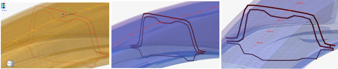
Figure 16. Section made of 3 thin parts. Without or with welds. - Contacts
- All domains like 3D region cuts or inflated domains (Figure 16) that remain disconnected are candidates for auto-contact. Auto-contact will internally generate kinematic equations to glue domains which are in proximity. The contact option has 3 values:
After welding lines and gluing domains, sectional properties are calculated as described above.