A surface represents the geometry associated with a physical part. A surface is a two-dimensional geometric entity that
may be used in automatic mesh generation.
Solids are closed volume of surfaces that can take any shape. Solids are three-dimensional entities that can be used in
automatic tetra and solid meshing.
A face is a single Non-uniform Rational B-Spline (NURBS) and is the smallest area entity. It has a separate underlying
mathematical definition, specified when it was created.
Drag surfaces, nodes, or lines along their normal direction, a vector, or another
line.
From the Geometry ribbon, Drag/Spin tool group, click the Drag
tool.
Optional: On the guide bar, click
to define additional options.
Choose between Surfaces, Nodes,
or Lines using the guide bar
selector.
Note: If Nodes is selected, a line will be drawn through
the specified nodes before dragging.
Select surfaces/nodes/lines and drag in the following ways:
Click to drag in a normal direction or click to define a direction using the Vector tool. Once a direction is defined, manipulate the
slider or enter a value in the microdialog.
Activate the Guides selector to drag along
selected guiding lines. Use the options in the microdialog to define how the geometry is dragged.
Fixed Frame
The geometry is only translated during the drag, not
rotated.
Line Tangent
In addition to the translation of the fixed frame option,
the geometry is also rotated in the same way that the
tangent of the line list rotates.
Frenet Frame
In addition to the translation and rotation of the Line
Tangent option, the geometry also rotates around the line
list tangent axis in the same way as the curvature vector
rotates.
The Frenet Frame option does not work well
when the curvature of the line list is not smooth or
includes large jumps.
Reverse Direction
Defines the drag in the opposite direction.
On the guide bar, click one of the following:
- Save changes and stay in the tool
- Save changes and close the tool
- Exit the tool without saving changes
Auto-Trim
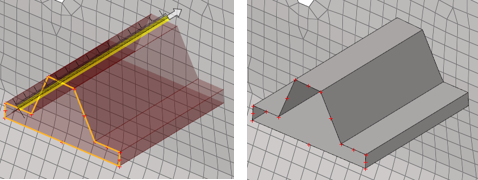
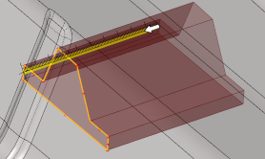
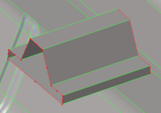
Use the auto-trim option in the microdialog when dragging nodes and lines.
While dragging lines or nodes, if a continuous surface or mesh is intersected and
this option is ON, the newly created surfaces are trimmed at the intersection. The
auto-trim option works for both geometry intersecting geometry and mesh. It also
works for FE topology intersecting FE topology.
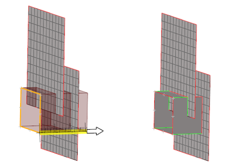
Note: With the auto-trim option ON, if the intersecting mesh or surfaces are not
continuous and have gaps as shown in Figure 4,
then the resulting surfaces can’t be trimmed completely. However, it will create
trim lines as shown in Figure 5.
But, since the complete surface is not trimmed, it wont be deleted.
When dragging lines, an option is available in the guide bar
menu () that allows you to stitch trimmed surfaces to the
target surfaces. Note that option is only applicable if auto-trim is turned
ON.