Define Engine Mesh (CAERO1)
Use the Engine Mesh tool to define the engine or missile modeling and meshing.
-
From the Aeroelasticity ribbon, click the
Engine Mesh tool.

Figure 1. -
Select the aerospace coordinate system CP to define the axis of the body.
The CAERO1 ID (EID) represents the element start ID with ID spanning along the body circumference.
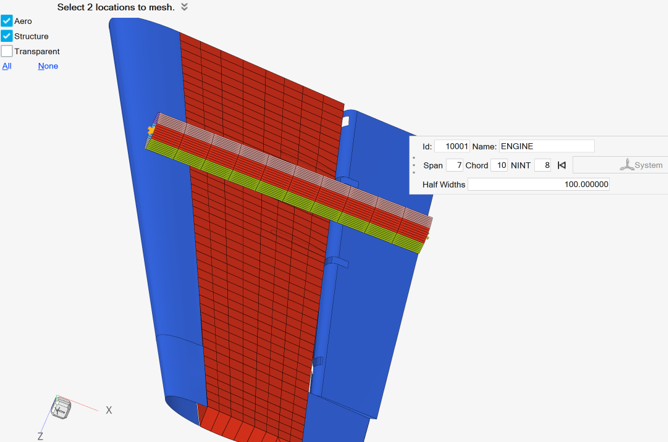
Figure 2. -
Set options as necessary by clicking
 on the guide bar.
-
On the guide bar, click one of the following:
 - Save changes and stay in the tool
 - Save changes and close the tool
Tip:
- From the Aeroelasticity ribbon, click the satellite
icon
 that appears
when you hover over the Engine Mesh tool to open the Aeroelasticity Browser.
that appears
when you hover over the Engine Mesh tool to open the Aeroelasticity Browser.